Hardware setup
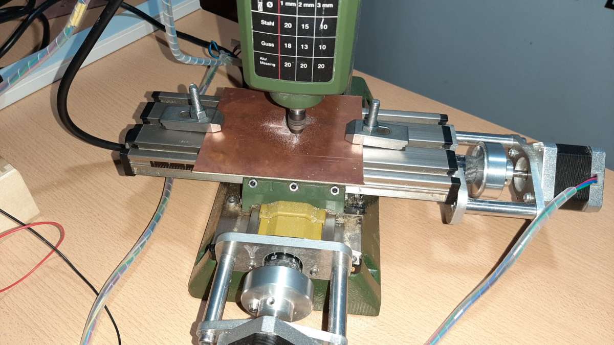
First, we have to build all the basic mechanical parts of the miller al put in each axis one of the stepper motors, then we have to attach two end-stop switches for each axis, one at the beginning of the rail, and the other at the end of the rail, and repeat this step for each axis, in this case, my miller machine only have 3 axis X, Y, and Z, and I used 6 end-stop switches and 3 stepper motors.
Once we finished all the mechanical construction (It's the hardest step), we have to join each stepper motor with one driver on the Arduino shield, and each end-stop switch with the Arduino shield as follows. Remember to follow the labels in drivers to connect X, Y, and Z-axis, and the same for the end-stop switches, they have labels such as X+ and X- to set the first (at beginning of the trail) and second (at the end on the trail) switch.

After wiring, we have to put the stepper drivers, but first, we have to calibrate the potentiometer in each little board, and we have to follow the datasheet, these case I'm using the drv8825 (link datasheet: https://www.ti.com/lit/ds/symlink/drv8825.pdf?ts=1630260587096&ref_url=https%253A%252F%252Fwww.google.com%252F) and we have to adjust the potentiometer until have:
$$V_{max} = I_{max}(8 * R)$$We have to replace this equation with the parameters of our stepper motor and driver. And then we have to put one driver for the axis in the CNC shield.
Finally, we have to connect our CNC shield to our Arduino UNO and also connect our power supply.
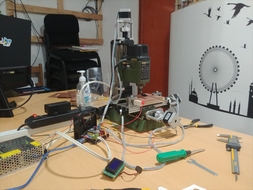
As you can see in the picture, we can connect a fan to the power supply and put it around of shield to avoid high temperatures.
Software Setup
First, we have to upload the firmware for the Arduino UNO, and I use the Grbl V1.1 CNC firmware because it is open-source and many companies support its development.
To upload the firmware, we only have to download the GitHub library and paste it on the Arduino libraries (as a common library) and open the default example it has and upload it to your board.
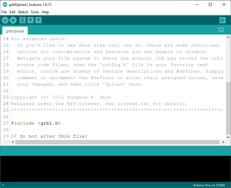
With the firmware ready we have to get an app to make the interface between the machine and us, and for this work, I decided to use UGS, It is another open-source project and also works for any operative system, in my case I use Linux and it a good solution.
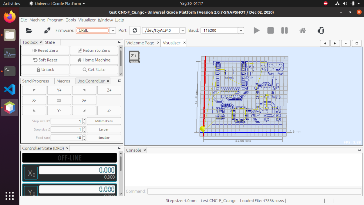
Now we have everything ready and we only have to make our test with our G-codes.
G-code
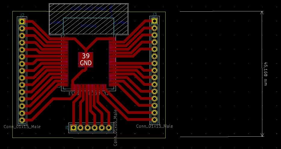
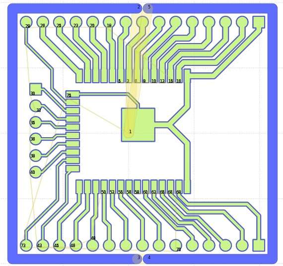
To create my codes for test my CNC machine I use Inkscape for random drawings and KiCad with FlatCAM
Results
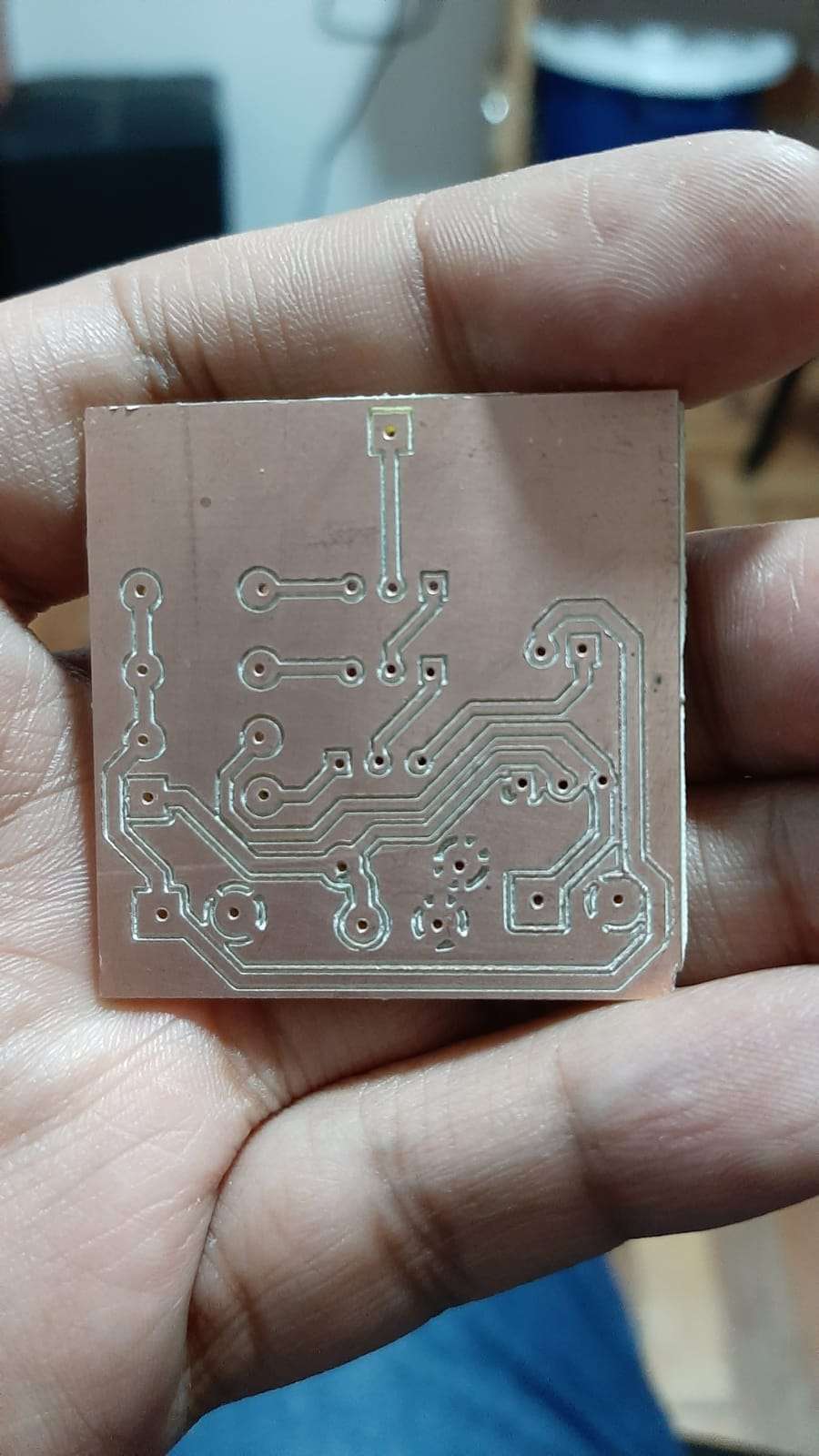
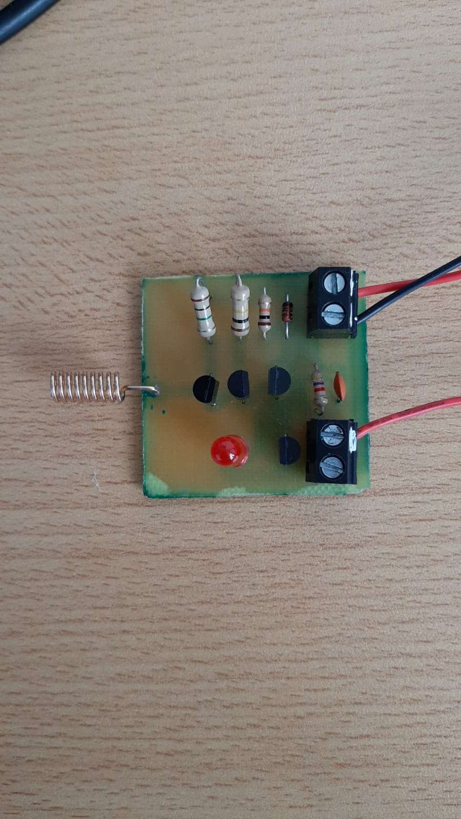
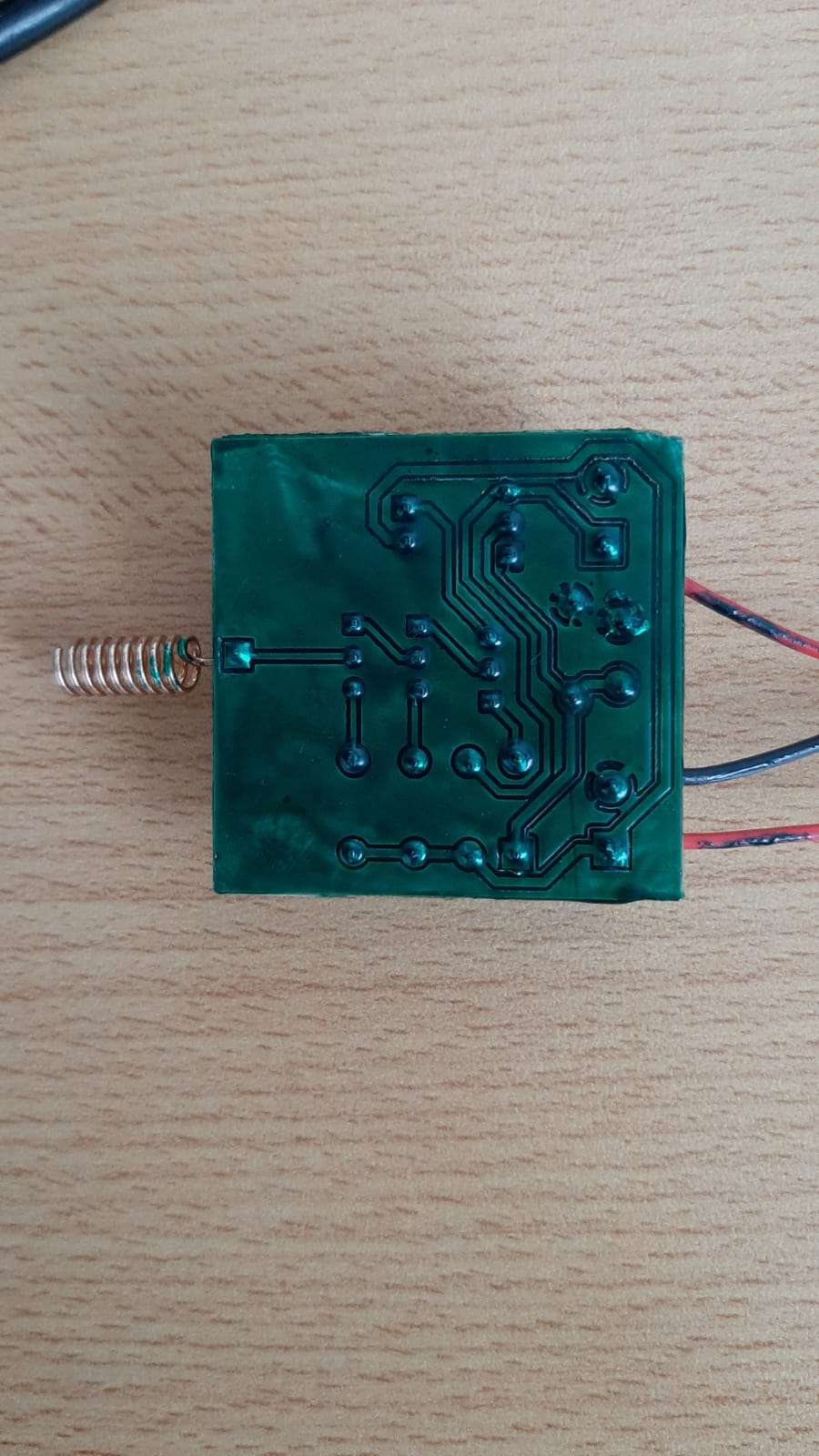
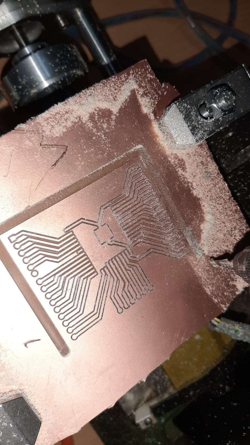
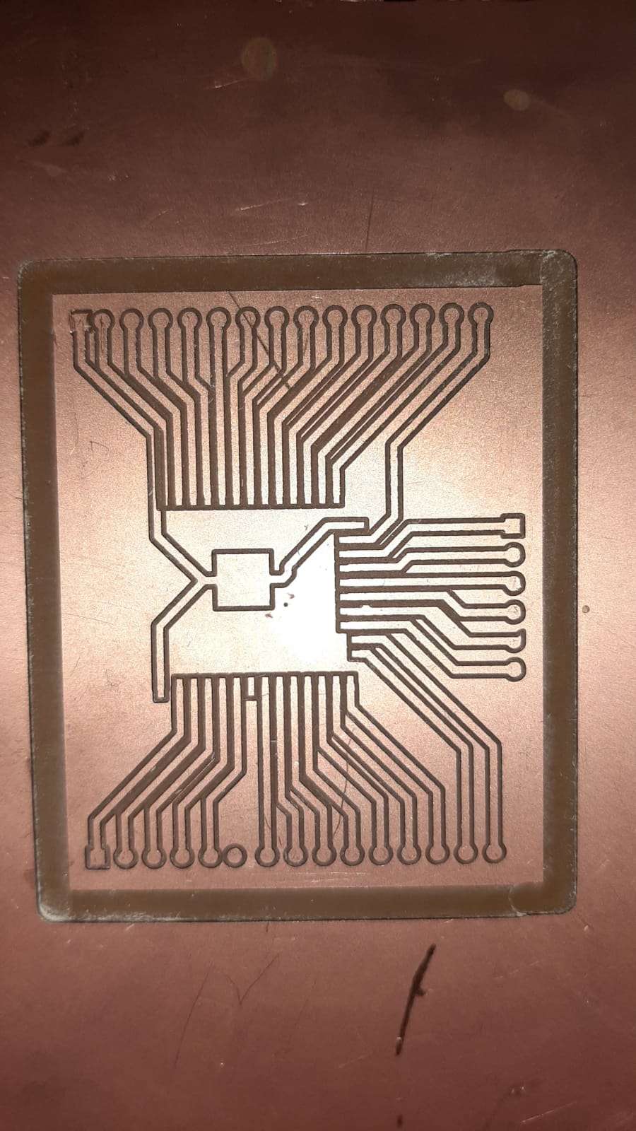
Whit this first test our results were amazing, it wasn't perfect but the quality was enough to solder the components of PCB.
Other Tests
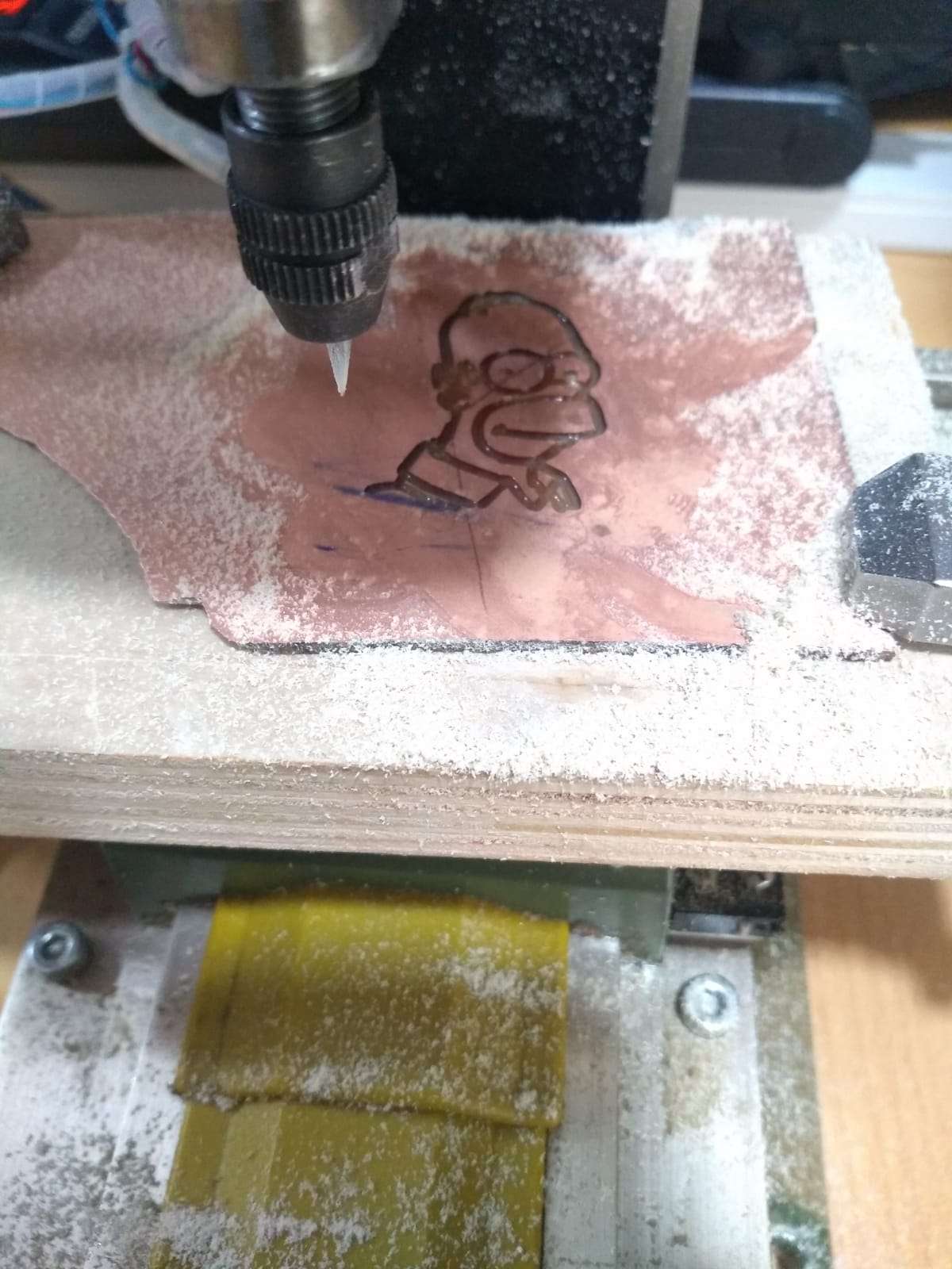
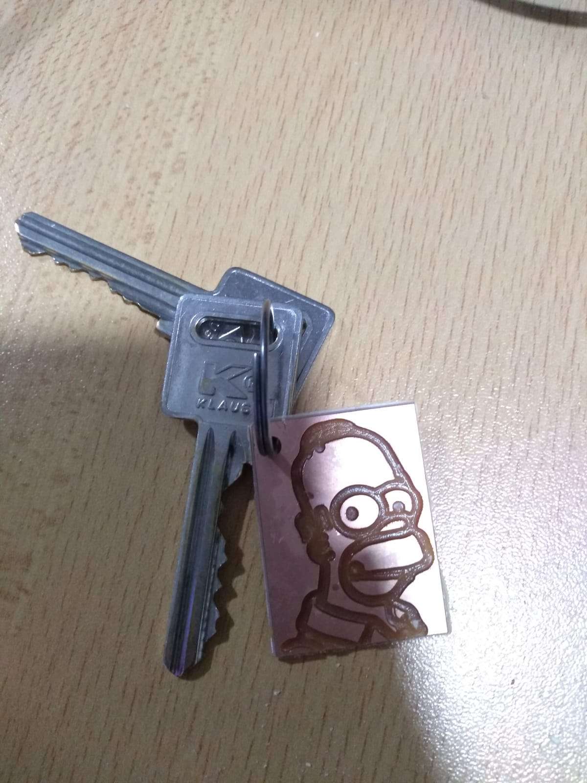
Making a Homer key chain
Making a PCB Through Hole
