I designed this around some acrylic 1/2" diameter half round material that I had on hand (cut to 20-7/16" long) to use as a lens that also serves to hold dovetail sections together. This can be readily purchased on internet for about $0.66 per foot, however, I have also included a model of a lens that can be printed in segments using clear filament.
STEP 1
Prepare LED strip (WS2812b LED strip individually addressable RGB Smart Pixel 30 LED's 1 meter long strip). Cut Strip into two (2) 15 LED segments and solder leads onto each segment at the beginning of each strip. Arrows on strip point 'AWAY' from where leads are needed.
STEP 2
Assemble all rail sections (one Outside Rail, and two Inside Rail segments per side) with case in the middle.
STEP 3
Feed leads from LED strips into case on each side, and adhere with backing tape. Note LED strips will stop about 1/2" from each Outside rail end
STEP 4
Slide Lens into each end all the way into the case to lock all dovetails in place. If using printed lens, there will be 4 required for each side. They are intended to bridge the dovetail areas.
STEP 5
Mount the assembly with end caps onto a backer board (I used 1/2" mdf that was cut to 2" wide by 45-1/8" long). Attach assembly using small pan head or flat-head screws (note: do not use round head, otherwise USB cable will not fit into slot later if needed for reprogramming parameters.)
STEP 6
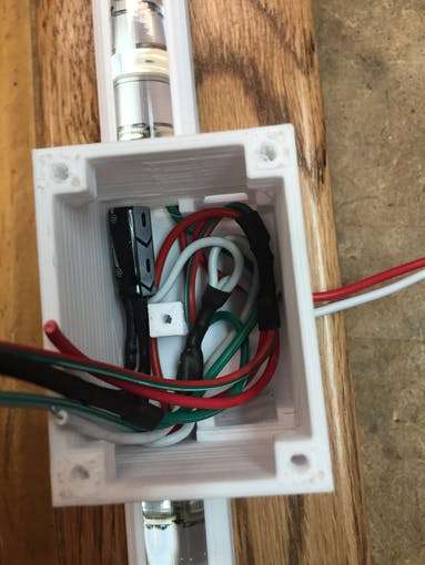
Wire up electronics. Note the location of capacitor. Capacitor is needed to prevent voltage spikes from supply. A resistor is used on signal wire (pin 7) for LEDs, and a diode is used on Arduino (V+) to prevent back feed of voltage in event USB is inserted without the power supply on. Without the diode, Arduino will try to supply voltage to LED's, causing excessive current through the on-board voltage regulated. Diode and resistor are soldered in-line with wiring, and covered with heat shrink tubing. The case will need to be drill from outside near bottom under Arduino to feed wires from power supply. I did not design this into model, as the size will depend what type wire is used. I recommend 18/2 wire be used. I used doorbell wire and put a connector just outside of case.
STEP 7
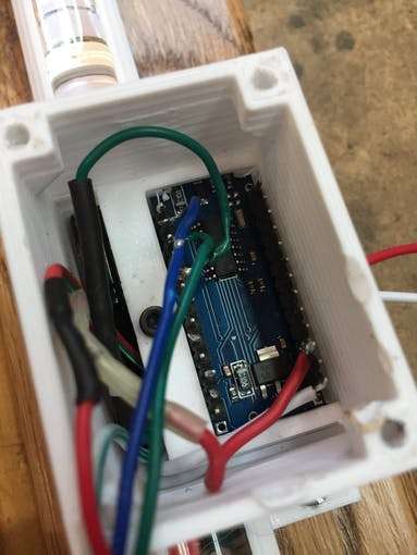
Use 2.5mm screw to hold down the Arduino, and complete wiring connections to Arduino. The holdown ends protrude into square holes on case. I removed the outermost pins on Arduino (unused) to make installation easier.
STEP 8
Use 2.5mm screws to attach ultrasonic detector (HC-SR02) to cover with hold down. Complete soldering connections to sensor. NOTE: make sure wires face toward center of sensor so as to not interfere with sidewall when assembling.
.jpg)
STEP 9
Install cover to case with 3mm screws.
STEP 10
Program Arduino using code below. Update your IDE libraries with 'FastLED' and 'QuickStats' prior to compiling your program. Note: Adjust parameters for 'startdistance' (point that sensor will first detect vehicle approach, as well as 'stopdistance' (final park spot of vehicle). Sensor range is 3 cm to 400 centimeters, so start and stop parameters need to be within these limits.
STEP 11
On garage door opener, install a lamp socket adapter with outlet built in. Plug in your 5VDC power supply to this line, and run to the light bar unit. The light bar will only be on from time door opens until the door light times out. This prevents light bar from always being on.
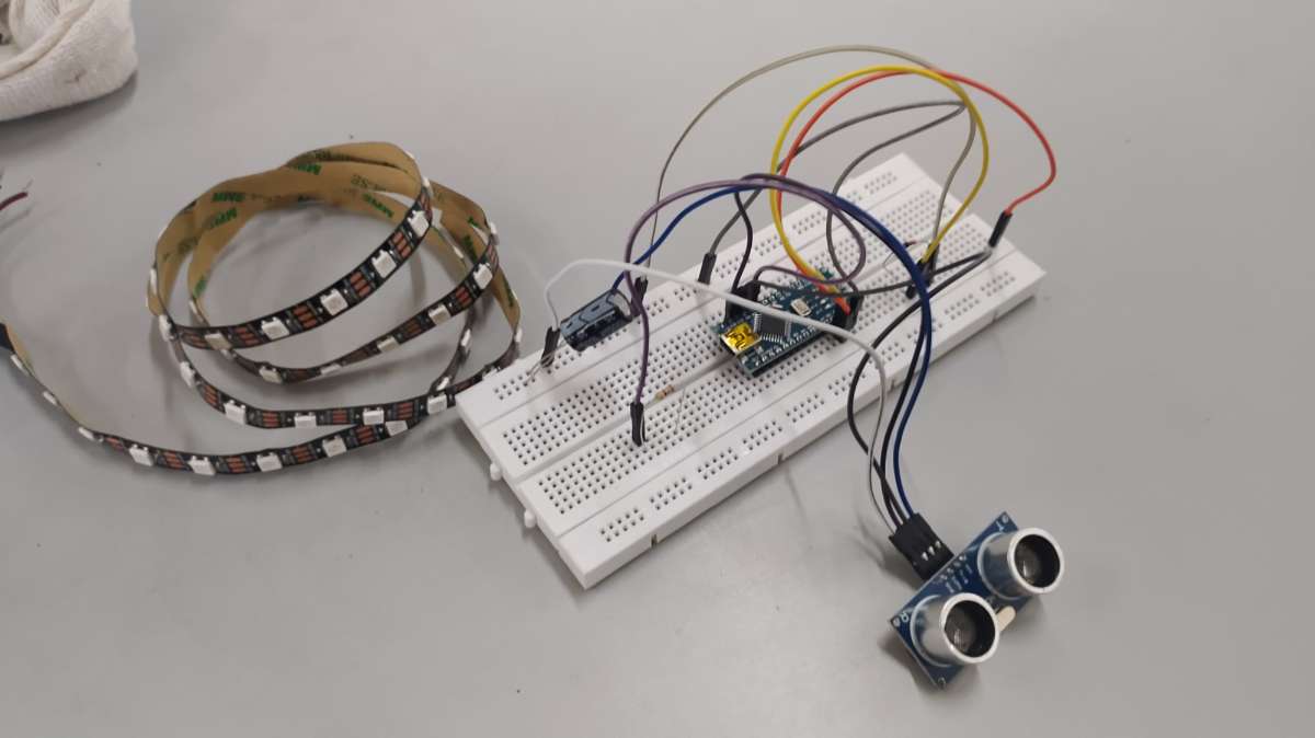
and the project connection in bred board system is as reference below