Let's make the circuit -
Connections
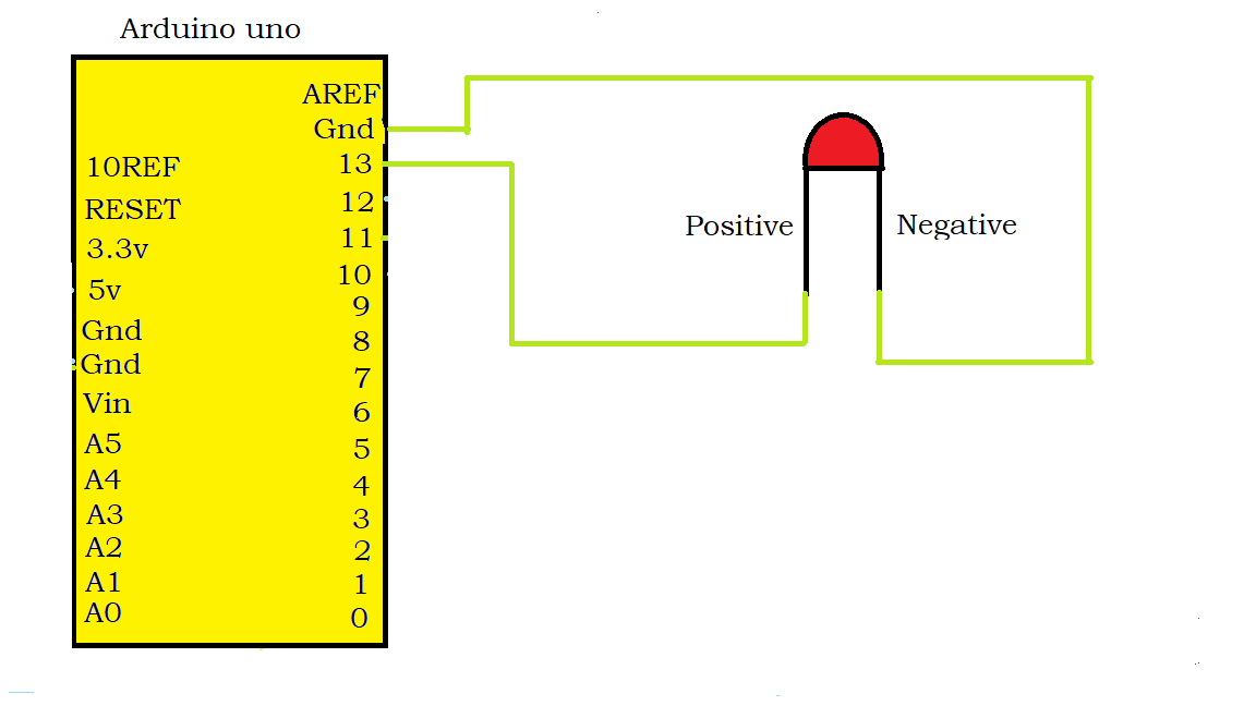
Light-emitting diode [ LED ]
Negative of led to Resistor
Resistor to Gnd of Arduino
Positive of led to pin no 13 of Arduino

Note - Actually I am using the LDR sensor module but I will show connections for both.
Connections
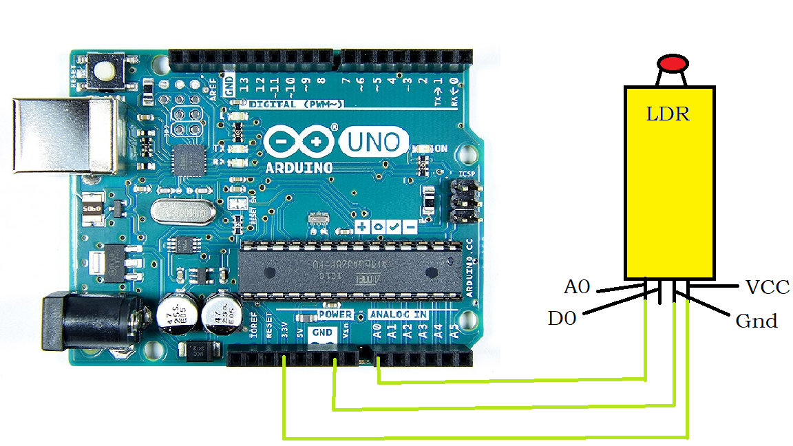
Light sensor module
A0 pin to A0 pin, Gnd to resistor
Resistor to Gnd of Arduino
VCC to 3.3v
No connections for pin D0

Note: These connections are if you have a single LDR sensor like shown here :

Connect one end of this sensor to one leg of the resistor
And another resistor to Gnd
Connect another leg of this sensor to Pin A0
Code
Here is the code :
const int ledPin = 13;
const int ldrPin = A0;
  void setup() {
  Serial.begin(9600);
  pinMode(ledPin, OUTPUT);
  pinMode(ldrPin, INPUT);
}
void loop() {
    int ldrStatus = analogRead(ldrPin);
    if (ldrStatus <= 800)
 {
   digitalWrite(ledPin, HIGH);
  Serial.print("Its Dark, Turn on the LED:");
  Serial.println(ldrStatus);
}
else  {
   digitalWrite(ledPin, LOW);
  Serial.print("Its Bright, Turn off the LED:");
  Serial.println(ldrStatus);
  }
}
When there is sufficient light the led will remain off.
And when there is darkness the led will remain on.
The threshold given in the code is 800.
Finally, the project is completed !!!
