
Hi,
Two years ago I made this replica of a Nanoleaf which was functional but not very appealing. https://www.hackster.io/Oniichan_is_ded/3d-printed-nanoleaf-attiny85-cb653d
In order to improve that project, I got this idea of making a WS2812B LED strip and connecting three of these strips together in a triangular shape to make a Nanoleaf like setup.

So I designed this PCB and gave it to JLCPCB for samples

So the goal of this project is to make a Different Nanoleaf like setup based on WS2812B powered by an Attiny85 with Neopixel Library!
Material Required
WS2812B RGB LEDs x 18

Arduino Nano ISP Programmer- (which I made in past to program Attiny85)
Custom PCB x 3 (provided by JLCPCB)
attiny85
100nF Capacitors SMD 0603 package x 18 (its recommended to use 1uF but I used 100nF and the setup worked fine)
USB Micro port
Thanks utsource for providing all the electronics components used in this project like WS2812B LEDs, 100nF CAP, and other stuff.
STEP 1
PCB Planning
So in order to make this setup, I first prepared its basic setup which was 18 SMD WS2812B RGB LED Connected with an Attiny85 and a button powered by a USB Micro port.
this was the Schematic-

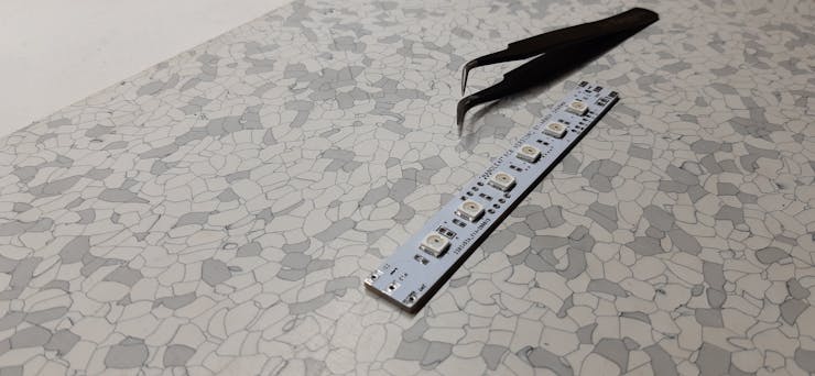
So after checking everything on a breadboard, I converted this schematic into a board file and made a PCB of 112mm x 12mm.

If you guys want to avoid the hassle of remaking this project's PCB, Ill leave the Gerber Data of this project's PCB so you can send that to a PCB manufacturer for samples!
STEP 2
Assembly
I first soldered WS2812B one by one on each LED STRIP board by a SOLDERING IRON (i don't have an SMT Blower at home so my only option was using the soldering iron, it too extra effort but everything turned out quite well and FUNCTIONAL)
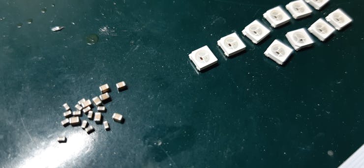
After that, I added SMD Capacitors to their assigned pads and the SOldering Job was Complete for now.
I tested the LED STRIP with a NodeMCU and Button setup.

After checking all three of these strips, I aligned them together one last time to solder Attiny85 on one of these Strips.

But Before soldering the Attiny, I put it on my Attiny programmer and Flashed the attiny85 with button cycler code which is a pretty common code of Neopixel library. (I changed few pinouts though) if you want to learn more about the Attiny programming process, you can check it out from here-https://www.hackster.io/Oniichan_is_ded/multiple-attiny85-13a-programmer-84adf8
#include <Adafruit_NeoPixel.h>

#define BUTTON_PIN   4  //D1- 5
                          // driven with a pull-up resistor so the switch should
                          // pull the pin to ground momentarily.  On a high -> low
                          // transition the button press logic will execute.

#define PIXEL_PIN    0   // Digital IO pin connected to the NeoPixels.//D4 - 2

#define PIXEL_COUNT 18

// Parameter 1 = number of pixels in strip,  neopixel stick has 8
// Parameter 2 = pin number (most are valid)
// Parameter 3 = pixel type flags, add together as needed:
//   NEO_RGB     Pixels are wired for RGB bitstream
//   NEO_GRB     Pixels are wired for GRB bitstream, correct for neopixel stick
//   NEO_KHZ400  400 KHz bitstream (e.g. FLORA pixels)
//   NEO_KHZ800  800 KHz bitstream (e.g. High Density LED strip), correct for neopixel stick
Adafruit_NeoPixel strip = Adafruit_NeoPixel(PIXEL_COUNT, PIXEL_PIN, NEO_GRB + NEO_KHZ800);

bool oldState = HIGH;
int showType = 0;

void setup() {
  pinMode(BUTTON_PIN, INPUT_PULLUP);
  strip.begin();
  strip.show(); // Initialize all pixels to 'off'
}

void loop() {
  // Get current button state.
  bool newState = digitalRead(BUTTON_PIN);

  // Check if state changed from high to low (button press).
  if (newState == LOW && oldState == HIGH) {
    // Short delay to debounce button.
    delay(20);
    // Check if button is still low after debounce.
    newState = digitalRead(BUTTON_PIN);
    if (newState == LOW) {
      showType++;
      if (showType > 9)
        showType=0;
      startShow(showType);
    }
  }

  // Set the last button state to the old state.
  oldState = newState;
}

void startShow(int i) {
  switch(i){
    case 0: colorWipe(strip.Color(0, 0, 0), 50);    // Black/off
            break;
    case 1: colorWipe(strip.Color(255, 0, 0), 50);  // Red
            break;
    case 2: colorWipe(strip.Color(0, 255, 0), 50);  // Green
            break;
    case 3: colorWipe(strip.Color(0, 0, 255), 50);  // Blue
            break;
    case 4: theaterChase(strip.Color(127, 127, 127), 50); // White
            break;
    case 5: theaterChase(strip.Color(127,   0,   0), 50); // Red
            break;
    case 6: theaterChase(strip.Color(  0,   0, 127), 50); // Blue
            break;
    case 7: rainbow(20);
            break;
    case 8: rainbowCycle(20);
            break;
    case 9: theaterChaseRainbow(50);
            break;
  }
}

// Fill the dots one after the other with a color
void colorWipe(uint32_t c, uint8_t wait) {
  for(uint16_t i=0; i<strip.numPixels(); i++) {
    strip.setPixelColor(i, c);
    strip.show();
    delay(wait);
  }
}

void rainbow(uint8_t wait) {
  uint16_t i, j;

  for(j=0; j<256; j++) {
    for(i=0; i<strip.numPixels(); i++) {
      strip.setPixelColor(i, Wheel((i+j) & 255));
    }
    strip.show();
    delay(wait);
  }
}

// Slightly different, this makes the rainbow equally distributed throughout
void rainbowCycle(uint8_t wait) {
  uint16_t i, j;

  for(j=0; j<256*5; j++) { // 5 cycles of all colors on wheel
    for(i=0; i< strip.numPixels(); i++) {
      strip.setPixelColor(i, Wheel(((i * 256 / strip.numPixels()) + j) & 255));
    }
    strip.show();
    delay(wait);
  }
}

//Theatre-style crawling lights.
void theaterChase(uint32_t c, uint8_t wait) {
  for (int j=0; j<10; j++) {  //do 10 cycles of chasing
    for (int q=0; q < 3; q++) {
      for (int i=0; i < strip.numPixels(); i=i+3) {
        strip.setPixelColor(i+q, c);    //turn every third pixel on
      }
      strip.show();

      delay(wait);

      for (int i=0; i < strip.numPixels(); i=i+3) {
        strip.setPixelColor(i+q, 0);        //turn every third pixel off
      }
    }
  }
}

//Theatre-style crawling lights with rainbow effect
void theaterChaseRainbow(uint8_t wait) {
  for (int j=0; j < 256; j++) {     // cycle all 256 colors in the wheel
    for (int q=0; q < 3; q++) {
      for (int i=0; i < strip.numPixels(); i=i+3) {
        strip.setPixelColor(i+q, Wheel( (i+j) % 255));    //turn every third pixel on
      }
      strip.show();

      delay(wait);

      for (int i=0; i < strip.numPixels(); i=i+3) {
        strip.setPixelColor(i+q, 0);        //turn every third pixel off
      }
    }
  }
}

// Input a value 0 to 255 to get a color value.
// The colours are a transition r - g - b - back to r.
uint32_t Wheel(byte WheelPos) {
  WheelPos = 255 - WheelPos;
  if(WheelPos < 85) {
    return strip.Color(255 - WheelPos * 3, 0, WheelPos * 3);
  }
  if(WheelPos < 170) {
    WheelPos -= 85;
    return strip.Color(0, WheelPos * 3, 255 - WheelPos * 3);
  }
  WheelPos -= 170;
  return strip.Color(WheelPos * 3, 255 - WheelPos * 3, 0);
}
SO after flashing the Attiny85 with the Code of this project, we can finally solder it on the LED STRIP and solder all three of these together.
But how does this setup works?
well the First Strip houses the Attiny85 setup, the Attiny's D0 is connected with Din of Ws2812B LED. that led is the starting point of this series. the Dout of the first strip is hooked up with Din of the second Strip and its Dout is connected with Din of the Third strip.

I have placed a Shorting resistor Pad in the strip LED strip which is connected in between Din of First LED of the FIrst strip, so if I want to control the strip with onboard Attiny, I just need to add a zero ohms resistor on that pad to short the connections.
STEP 3
Final hookup
I soldered the led strips together by pads on edge with help of this jig I made for making things a little easier.

the Technique I'm using here is pretty crude and simple, just put soldering iron in between pads and apply lots of Solder LEAD.
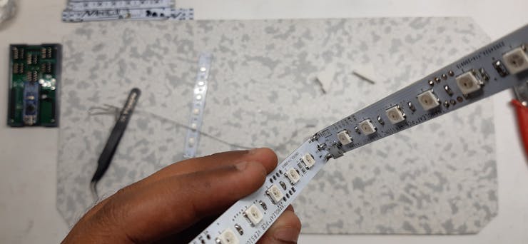
This project didn't have any problem and worked at the first powerup.
End results were satisfying and GREAT.

you guys can check out this project's video for the more detailed and better tutorial which is available on my youtube channel -
version 2 of this project will be powered by an ESP12F and a standalone battery.
Check out my Instagram acc if you want updates on this project
Leave a comment if you have any problem with this project!