.png)
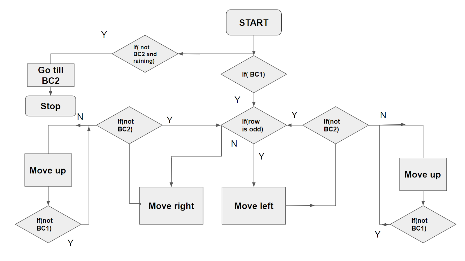
Flow Chart
By comparing the factor of safeties 1.5 mm plate is sufficient for the application.
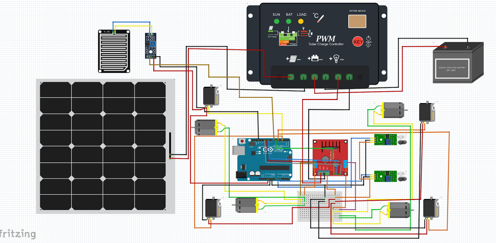
Circuit Diagrams: :
Arduino Circuit:
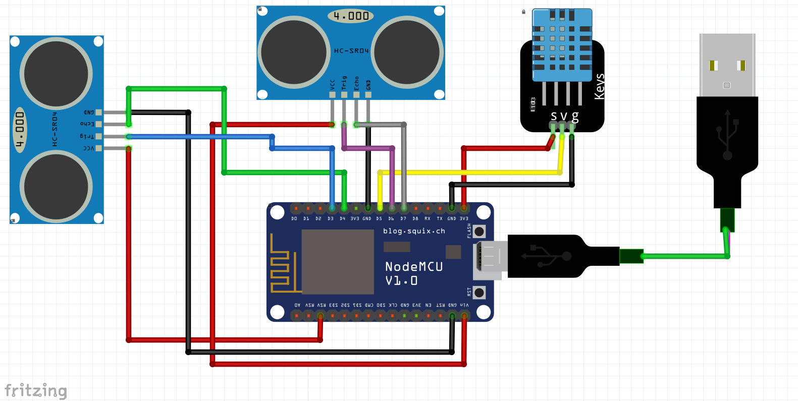
Node MCU Circuit:
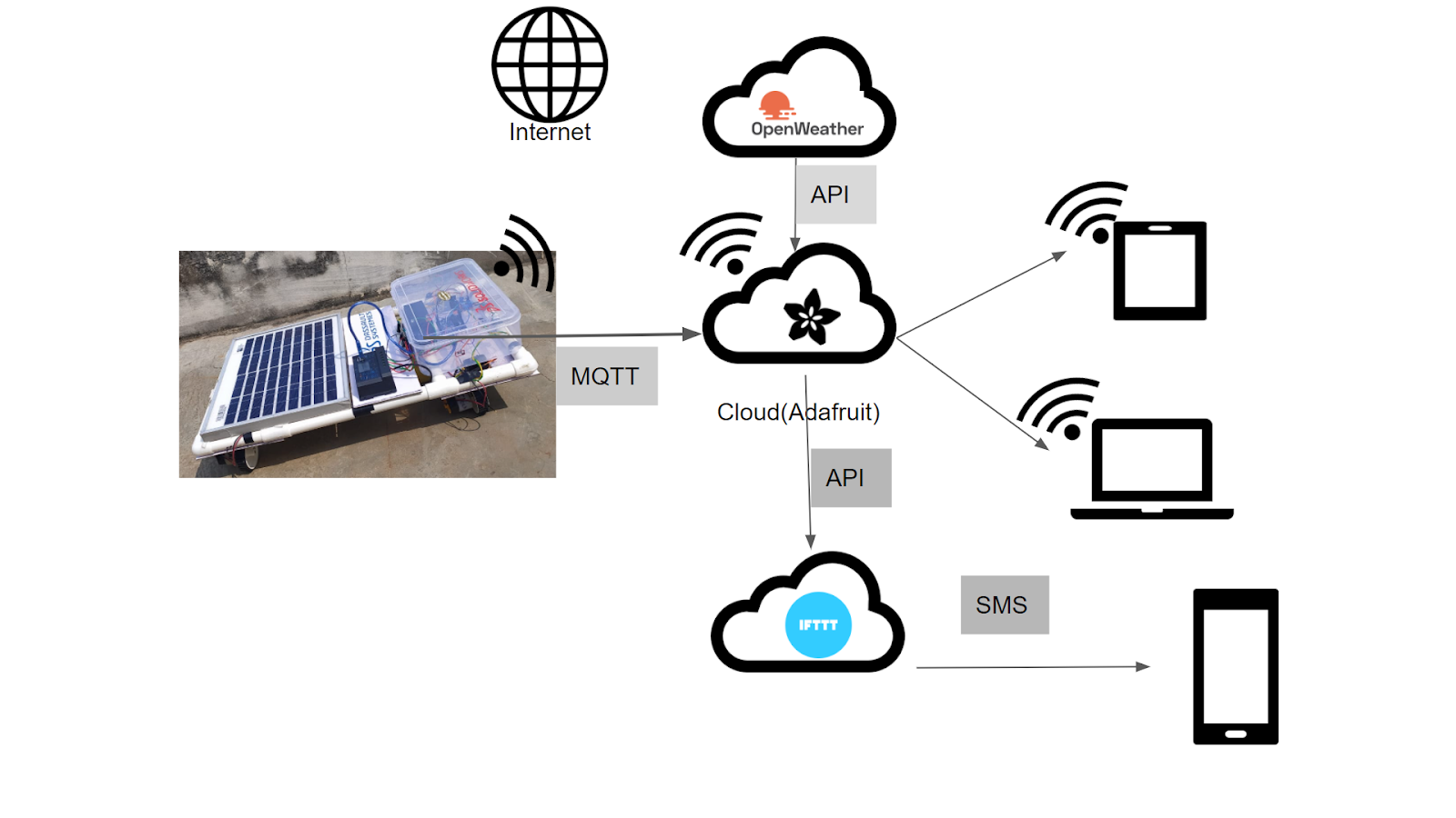
IOT Network:
Dashboard:
Here, in this project we have implemented the IOT technology to monitor the position of robots in the grid. And moreover, the dashboard is designed to monitor the environmental traits like temperature, humidity and wind speed. Data source for future analysis and visualization. The temperature, humidity and wind speed data plotted against the timestamp for visualization.
The interface look like given below:
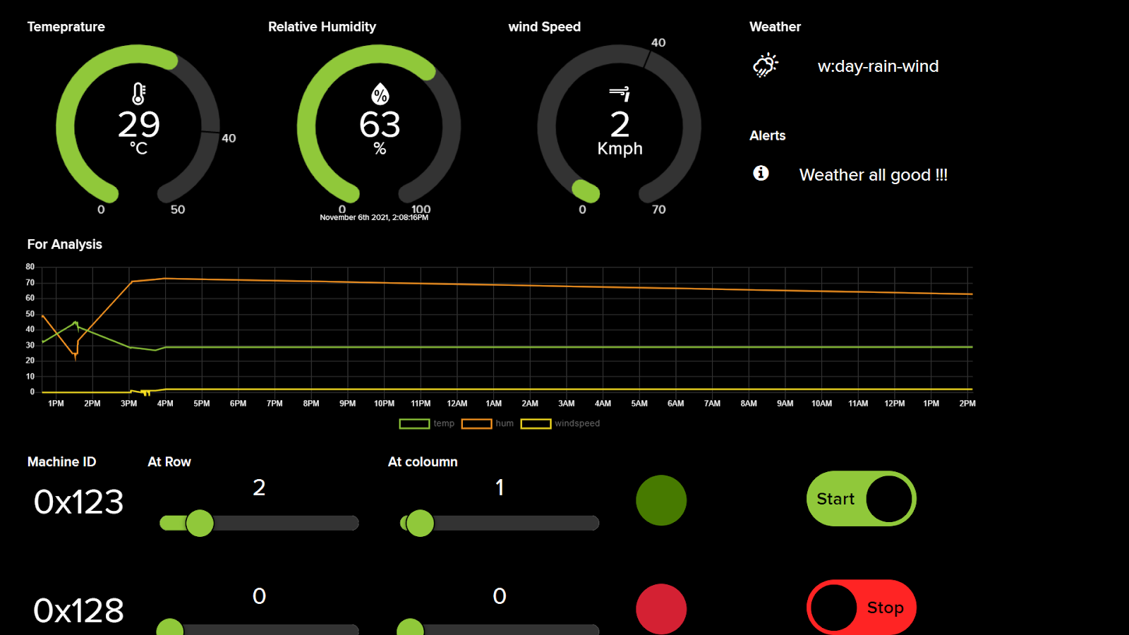
Fig 4.2 Dashboard
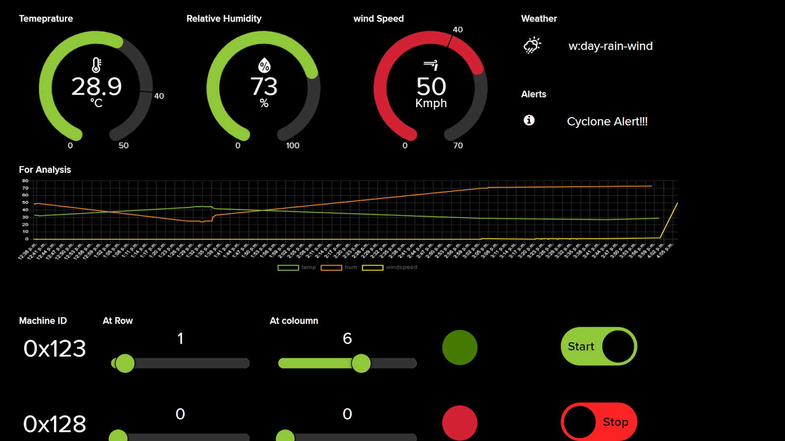
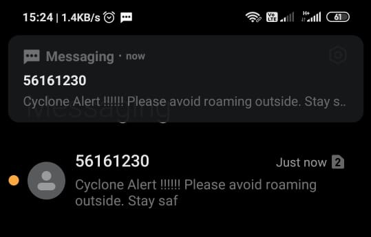
Temperature, humidity and wind speed are represented in the form of gauges. The weather section gives information about sun and rain. The alerts section gives warnings in case of heavy wind speed as “cyclone alert!!!” and SMS alert shown below:
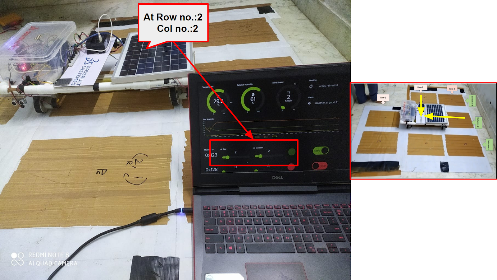
Machine ID used to differentiate the robots, if there were many such robots working in the field. The fields row and column gives the current row and column status of the robot respective to machine ID.
Example shown below:
ARDUINO Code:
https://docs.google.com/document/d/1JQKwOYQ6spv7RU7eKZEQXtONA-yuDDJ80EK3tR0Sy7A/edit?usp=sharing
Node MCU Code:
https://docs.google.com/document/d/1pV3s5wXMAJR7m18Xmc5EbNdsD6kSC44qqxPlhG0twbA/edit?usp=sharing
Final project video:
Business Viability as a Product:
(0).png)
(0).png)
(0).png)