
Gather Components and Tools: Begin by gathering all necessary components: Atmega328p microcontroller, RS485 Modbus module, LEDs, resistors, capacitors, a 16MHz crystal oscillator, socket connector, and a push button. Ensure you have the development environment, including the Arduino IDE and a Modbus library, as well as PCB design software like KiCad. Additionally, have a breadboard, jumper wires, and a power supply ready.
Set Up the Development Environment: Install the Arduino IDE from the official website and set it up on your computer. Open the Arduino IDE and go to Sketch > Include Library > Manage Libraries. Search for and install a suitable Modbus library, such as "ModbusMaster" by Doc Walker, which will be used to facilitate communication via the Modbus protocol.
Design the Circuit on Breadboard: Start by connecting the Atmega328p microcontroller on the breadboard. Connect Vcc and GND to the power rails and connect a 16MHz crystal oscillator between pins 9 and 10 (XTAL1 and XTAL2) with 22pF capacitors from each pin to ground. Connect a 10kΩ pull-up resistor between pin 1 (RESET) and Vcc. For the RS485 Modbus module, connect the RO (Receiver Output) pin to the RX pin of Atmega328p (pin 2) and the DI (Driver Input) pin to the TX pin of Atmega328p (pin 3). Tie DE (Driver Enable) and RE (Receiver Enable) pins together and connect them to a digital pin on the Atmega328p (e.g., pin 4). Connect Vcc and GND to the power rails. Add LEDs to digital pins of the Atmega328p through 220Ω current-limiting resistors and connect one side of the push button to ground and the other to a digital pin (e.g., pin 5) with a 10kΩ pull-up resistor to Vcc.
Program the Atmega328p Microcontroller: Use an Arduino UNO as an ISP programmer to upload the sketch to the Atmega328p. Follow the Atmega328p standalone setup guide to configure the Arduino UNO for this purpose. Write a sketch in the Arduino IDE to configure the Atmega328p for Modbus communication, initializing the serial communication and Modbus with a slave ID. For example, use ModbusMaster to read holding registers and control LEDs based on successful communication. Upload the code by selecting the appropriate board and port in the Arduino IDE.
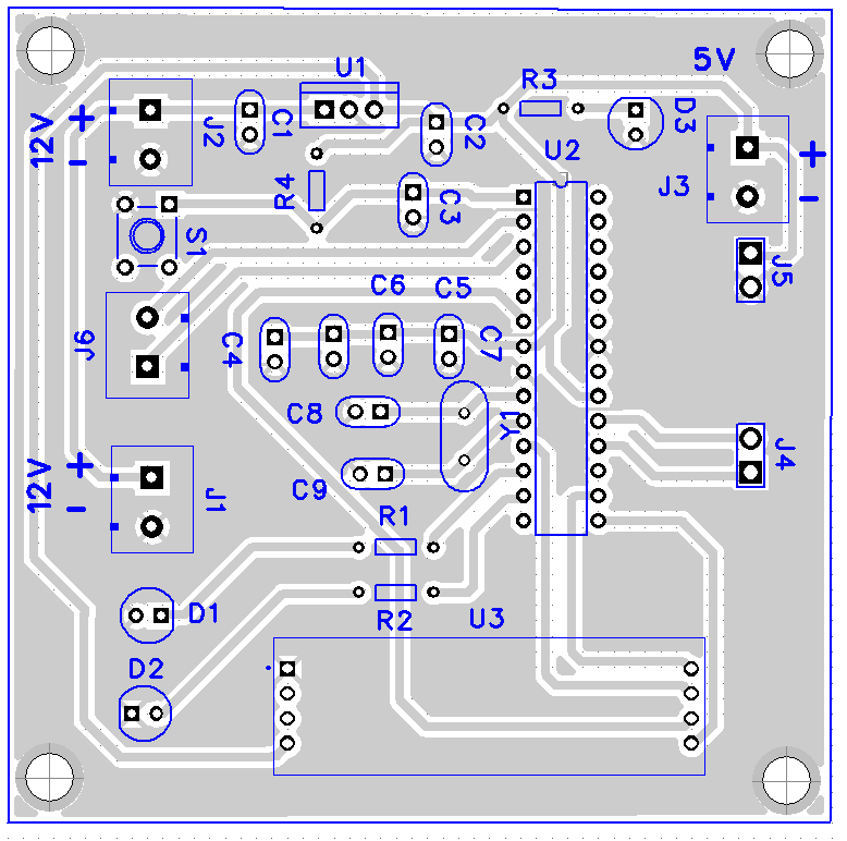
Design and Fabricate the PCB: Transfer the breadboard design to KiCad or another PCB design software. Place all components, including the Atmega328p, RS485 module, connectors, LEDs, and push button, on the PCB layout, ensuring proper routing of traces between components. Send the PCB design files to a manufacturer or use DIY methods to fabricate the PCB.
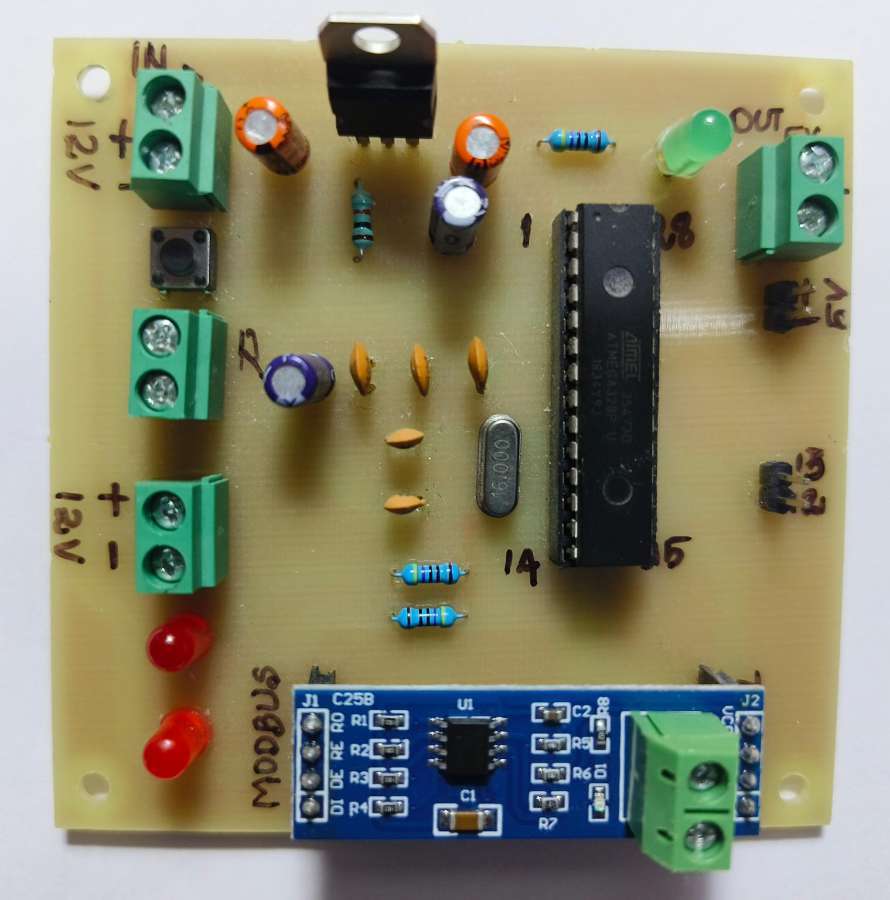
Assemble the PCB: Solder all components, including the Atmega328p, RS485 module, LEDs, resistors, capacitors, crystal oscillator, socket connector, and push button onto the fabricated PCB. Verify all connections for accuracy, ensuring there are no shorts or open circuits.
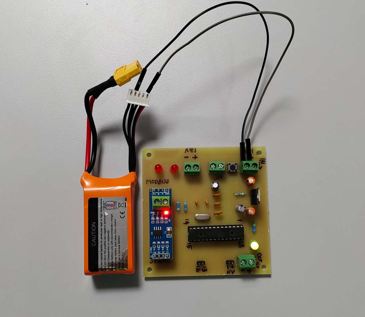
Test the Modbus Communication: Connect the Modbus-enabled controller to a Modbus network using the RS-485 interface. Configure all devices properly to use the Modbus protocol. Use a Modbus master device to read and write data to the Modbus controller, ensuring the communication is working as expected by monitoring data exchange.
Implement in Industrial Environment: Integrate the Modbus-enabled controller with PLCs within the industrial environment using the RS-485 interface. Ensure all devices are configured correctly to use the Modbus protocol, allowing for real-time monitoring and control to optimize the performance and reliability of the system.
Testing and Validation: Conduct comprehensive testing under various conditions to ensure the robustness of the communication system. Validate the integrity of data and response times, debugging any issues that arise during testing. Optimize the code and configuration for better performance and reliability.
Documentation and Maintenance: Create detailed documentation covering the setup, configuration, and usage of the Modbus-enabled controller. Establish a maintenance plan to ensure the system's long-term reliability and performance, addressing any potential issues promptly.