1. INTRODUCTION
Robotics is expected to play a major role in the agricultural domain, and often multi-robot systems and collaborative approaches are mentioned as potential solutions to improve efficiency and system robustness. Among the multi-robot approaches, swarm robotics stresses aspects like flexibility, scalability and robustness in solving complex tasks, and is considered very relevant for precision farming and large-scale agricultural applications. This Agribot gives an advance method to harvesting and watering the crops with minimum man power and labor making it an efficient vehicle. Moreover, the vehicle can be controlled through Internet medium using an Android smart phone. The whole process calculation, processing, monitoring is designed with motors & sensor interfaced with microcontroller. Using Internet of things, the robot is controlled. In excess of 40 percent of the population on the planet picks agribusiness as the essential occupation. Lately, expanded interest has been developed for the development of the self-ruling vehicles like robots in the agribusiness. In traditional strategy for farming works, the types of equipment used to perform various activities are costly and badly designed to deal with. In this way, farmers need advanced equipment to perform farming procedures.
2. PROJECT BUILDING
STEP 1
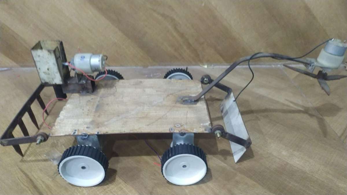
- Make a right metal chassis required for the project, mount Geared DC motors to the chassis and attach wheels to the motors as shown in figure.
- Also you can attach belt drives instead of wheels to the robot as per your needs.
STEP 2
- Short the polarities of two motors of each side and then connect it to the motor driver, give power supply of 9-12V to the driver.
- Here I had used 12v Lithium battery as a power unit.
- Then connect IN1, IN2, IN3, IN4 of driver to 8,7,4,3 of node mcu and ENABLE A & B to 5,6 of mcu as shown in figure.
- You can use 5V output of driver to power up node mcu.
- The pin diagram is shown below, the code is given in code block section.
STEP 3
Upload the given code to node mcu of the Master Robot using Arduino software.

#include <ESP8266WiFi.h>
#include <BlynkSimpleEsp8266.h>
#include <RH_NRF24.h>
#include <EEPROM.h>

 RH_NRF24 nrf24(2, 4); // use this for NodeMCU Amica/AdaFruit Huzzah ESP8266 Feather


int deviceID = EEPROM.read(0);

char auth[] = BLYNK_AUTH_TOKEN;

// Your WiFi credentials.
// Set password to "" for open networks.
char ssid[] = "Softronic";
char pass[] = "sunsoftronic";
bool eventTrigger = false;
BlynkTimer timer;

int m1Clock=D8;
int m1AntiClock=D7;
int m2Clock=D6;
int m2AntiClock=D5;
int m3=D1;
int m4=D3;

int m6AntiClock=D0;

void setup()
{
  // Debug console
  Serial.begin(9600);

  Blynk.begin(auth, ssid, pass);
  pinMode(m1Clock,OUTPUT);
  pinMode(m1AntiClock,OUTPUT);
  pinMode(m2Clock,OUTPUT);
  pinMode(m2AntiClock,OUTPUT);
  pinMode(m3,OUTPUT);
  pinMode(m4,OUTPUT);

  pinMode(m6AntiClock,OUTPUT);


  while (!Serial)
    ; // wait for serial port to connect. Needed for Leonardo only
  if (!nrf24.init())
  {
    Serial.println("init failed");

  }
  // Defaults after init are 2.402 GHz (channel 2), 2Mbps, 0dBm
  if (!nrf24.setChannel(3))
  {
    Serial.println("setChannel failed");
  }
  if (!nrf24.setRF(RH_NRF24::DataRate2Mbps, RH_NRF24::TransmitPower0dBm)) {
    Serial.println("setRF failed");
  }
  Serial.println("Transmitter started");
}
int fwd,wat,lft,right,cut,seed;
void loop()
{
  Blynk.run();
  uint8_t data[7];//int fwd,wat,lft,right,cut,seed;

  data[0] = fwd;
  data[1] = lft;
  data[2] = right;
  data[3] = wat;
  data[4] = cut;
  data[5] = seed;
  data[6] = deviceID;


  nrf24.send(data, sizeof(data));
  nrf24.waitPacketSent();


}


BLYNK_WRITE(V7){
  int val=param.asInt();
  if(val){
    fwd=1;
    digitalWrite(m1AntiClock,HIGH);
    digitalWrite(m2AntiClock,HIGH);
    Blynk.virtualWrite(V0,"Forward Start");
  }else{
    fwd=0;
    digitalWrite(m1AntiClock,LOW);
    digitalWrite(m2AntiClock,LOW);
    Blynk.virtualWrite(V0,"Forward stop");
  }
}

BLYNK_WRITE(V6){
  int val=param.asInt();
  if(val){
    lft=1;
    digitalWrite(m1AntiClock,HIGH);
    digitalWrite(m2Clock,LOW);
    Blynk.virtualWrite(V0,"Left Start");
  }else{
    lft=0;
    digitalWrite(m1AntiClock,LOW);
    digitalWrite(m2Clock,LOW);
    Blynk.virtualWrite(V0,"Left stop");
  }
}

BLYNK_WRITE(V5){
  int val=param.asInt();
  if(val){
    right=1;
    digitalWrite(m1Clock,LOW);
    digitalWrite(m2Clock,LOW);
    digitalWrite(m2AntiClock,HIGH);
    Blynk.virtualWrite(V0,"Right Start");
  }else{
    right=0;
    digitalWrite(m2Clock,LOW);
    digitalWrite(m2AntiClock,LOW);
    Blynk.virtualWrite(V0,"Right stop");
  }
}

BLYNK_WRITE(V4){
  int val=param.asInt();
  if(val){
    seed=1;
    digitalWrite(m3,HIGH);
    Blynk.virtualWrite(V0,"Sedding");
  }else{
    seed=0;
    digitalWrite(m3,LOW);
    Blynk.virtualWrite(V0,"........");
  }
}

BLYNK_WRITE(V3){
  int val=param.asInt();
  if(val){
   cut=1;
    digitalWrite(m4,HIGH);
    Blynk.virtualWrite(V0,"Harvester");
  }else{
    cut=1;
    digitalWrite(m4,LOW);
    Blynk.virtualWrite(V0,"........");
  }
}


BLYNK_WRITE(V1){
  int val=param.asInt();
  if(val){
    wat=1;
      digitalWrite(m6AntiClock,HIGH);
       Blynk.virtualWrite(V0,"WATER PUMP");
  }
  else
  {
   wat=0;
    digitalWrite(m6AntiClock,LOW);
     Blynk.virtualWrite(V0,"------------");
  }
}
STEP 4
Upload the given code to node mcu of the Slave Robot using Arduino software.

#include <RH_NRF24.h>

#include <EEPROM.h>

 RH_NRF24 nrf24(2, 4); // use this for NodeMCU Amica/AdaFruit Huzzah ESP8266 Feather
#define DHTPIN D1
//#define DHTPIN 2

#define DHTTYPE DHT11
DHT dht(DHTPIN, DHTTYPE);

int deviceID = EEPROM.read(0);


int m1Clock=D8;
int m1AntiClock=D7;
int m2Clock=D6;
int m2AntiClock=D5;
int m3=D1;
int m4=D3;

int m6AntiClock=D0;

void setup()
{
  // Debug console
  Serial.begin(9600);


  pinMode(m1Clock,OUTPUT);
  pinMode(m1AntiClock,OUTPUT);
  pinMode(m2Clock,OUTPUT);
  pinMode(m2AntiClock,OUTPUT);
  pinMode(m3,OUTPUT);
  pinMode(m4,OUTPUT);

  pinMode(m6AntiClock,OUTPUT);


  if (!nrf24.init())
  {
    Serial.println("init failed");

  }
  // Defaults after init are 2.402 GHz (channel 2), 2Mbps, 0dBm
  if (!nrf24.setChannel(3))
  {
    Serial.println("setChannel failed");
  }
  if (!nrf24.setRF(RH_NRF24::DataRate2Mbps, RH_NRF24::TransmitPower0dBm)) {
    Serial.println("setRF failed");
  }
  Serial.println("Transmitter started");
}
int fwd,wat,lft,right,cut,seed;
void loop()
{

  // Now wait for a reply
  uint8_t buf[RH_NRF24_MAX_MESSAGE_LEN];
  uint8_t len = sizeof(buf);

  if (nrf24.waitAvailableTimeout(1000))
  {
    // Should be a reply message for us now
    if (nrf24.recv(buf, &len))
    {

      Serial.print("got reply: ");
      Serial.println((char*)buf);
    }
    else
    {

      Serial.println("recv failed");
    }
  }
  else
  {
    Serial.println("No reply.");

  }
 int val=buf[0];
  if(val){

    digitalWrite(m1AntiClock,HIGH);
    digitalWrite(m2AntiClock,HIGH);

  }else{

    digitalWrite(m1AntiClock,LOW);
    digitalWrite(m2AntiClock,LOW);

  }

  int val1=buf[1];
  if(val1){

    digitalWrite(m1AntiClock,HIGH);
    digitalWrite(m2Clock,LOW);

  }else{

    digitalWrite(m1AntiClock,LOW);
    digitalWrite(m2Clock,LOW);

  }
int val2=buf[2];
  if(val2){

    digitalWrite(m1Clock,LOW);
    digitalWrite(m2Clock,LOW);
    digitalWrite(m2AntiClock,HIGH);

  }else{

    digitalWrite(m2Clock,LOW);
    digitalWrite(m2AntiClock,LOW);

  }
  int val3=buf[3];
  if(val3){

    digitalWrite(m3,HIGH);

  }else{

    digitalWrite(m3,LOW);

  }

   int val4=buf[4];
  if(val4){

    digitalWrite(m4,HIGH);

  }else{

    digitalWrite(m4,LOW);

  }
   int val5=buf[5];
  if(val5){

      digitalWrite(m6AntiClock,HIGH);

  }
  else
  {

    digitalWrite(m6AntiClock,LOW);

  }
}
STEP 5
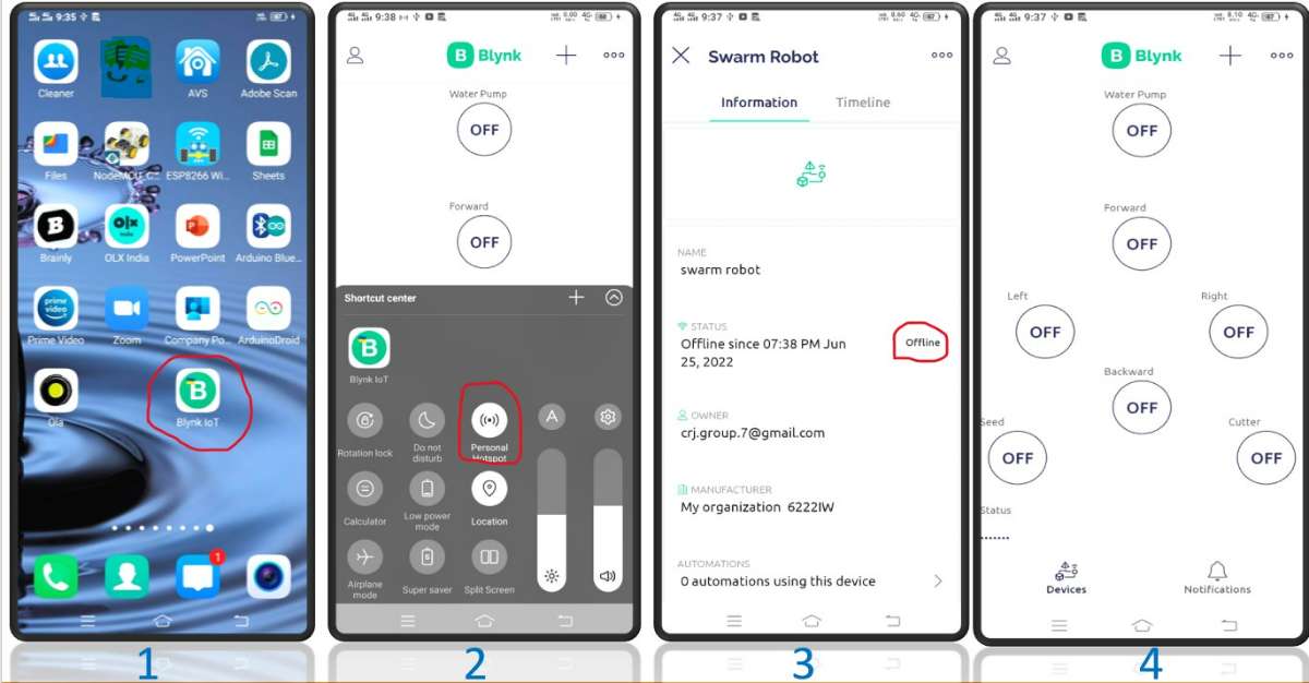
- Download Blynk IOT app from play store in your mobile.
- Make necessary configurations using SSID network & password.
- Connect the robot to mobile using hotspot network to control the movements.
STEP 6
- APP INTERFACE
3. DEMONSTRATION VIDEO
4. BRIEF DESCRIPTION
ABSTARCT
Robotics is expected to play a major role in the agricultural domain, and often multi-robot systems and collaborative approaches are mentioned as potential solutions to improve efficiency and system robustness. Among the multi-robot approaches, swarm robotics stresses aspects like flexibility, scalability and robustness in solving complex tasks, and is considered very relevant for precision farming and large-scale agricultural applications. This Agribot gives an advance method to harvesting and watering the crops with minimum man power and labor making it an efficient vehicle. Moreover, the vehicle can be controlled through Internet medium using an Android smart phone. The whole process calculation, processing, monitoring is designed with motors & sensor interfaced with microcontroller. Using Internet of things, the robot is controlled.
Keywords: Agriculture, Agribot, Robotics, IOT, Wi-Fi, Android Application, Embedded System.
INTRODUCTION
In India there are 70 percentage of population chooses agriculture as a primary occupation. In the current generation we do not have sufficient skilled man power specifically in agricultural sector. A manual farming consumes more time & leads to more pollution. The main purpose for developing Automation in Agricultural field is decreasing labor and decreasing time required to perform the processes on crops so that human efforts will get reduce up to 90 percent. Automation is required for safety and health of workers especially when worker have to perform harmful duties. Some of the previously developed robotics applications are Crop Seeding it involves autonomous precision seeding combines robotics with geomapping. Crop Monitoring and Analysis is provided by drone companies like Precision Hawk offers farmer combined packages which include robotic hardware and analysis software. Other applications are Fertilizing and irrigation system, Crop weeding and spraying system, Autonomous tractors, Picking and harvesting system. In the field of agriculture, various operations for handling heavy material are performed. For example, in vegetable cropping, workers should handle heavy vegetables in the harvest season. Additionally, in organic farming, which is fast gaining popularity, workers should handle heavy compost bags in the fertilizing season. These operations are dull, repetitive, or require strength and skill for the workers. In the 1980’s many agricultural robots were started for research and development. Kawamura and co-workers developed the fruit harvesting in orchard. Grand and co-workers developed the apple harvesting robot. However, many of the robots are not in the stages of diffusion but still in the stages of research and development. It is important to find rooms to achieve higher performance and lower cost of the robots. The system uses basic components like Solar panel, DC motor, Battery, Relay, Motor driver, Relay driver, Bluetooth Module and PIC18F4520 controller. The whole process is controlled by microcontroller. The solar panel is used to charge the battery. This battery used to power vehicle movement as well as to the motor that is used for grass cutting. The ploughing of field and plantation of seed is done by using DC motor. Distance between the two seeds is controlled and varied by using microcontroller. When the robot reaches the end of the field, we can change the direction with the help of Bluetooth command. The advantage of this solar powered multi-function Agri-robot is that it does not require any fuel or petrol to work, as it works on the solar energy. The circuit model is less complex and compact due the use of PIC18F4520 controller.
PROBLEM STATEMENT
The farmers are ought to follow a traditional naked eye observation and yielded healthy crops without the involvement of chemicals for animals and also to their cultivation land in order to keep healthy diversity.
For each process separate robot is used such as,
- Demeter (used for harvesting)
- Robot for weed control (wild plants)
- Robot for seeding
- Robot for fertilization.
OBJECTIVES
- The main aim of this Project is to Propose an IOT based Agribot and agriculture data acquisition using swarm robotics.
- To measure temperature and humidity in the field and turn on the Water pump.
- To harvest the field and weed cutting.
- To sow the seeds
METHODOLOGY
On basis of the survey Literatures and after referring various technical papers a new and innovative project idea was developed. The aim of the project ‘SAGA’ was to build a group of robots which would construct an input schematic given by the user on a given platform. In Our Project we have Two Robots, one is Master Robot and second is Slave robot, Swarm robotics means the instruction we given to the Master Robot will Followed by Slave Robot. In our Project also we are used the same technique for example, In Mobile App we will control the Agribot, Initially I will instruct the Robot to move forward via Mobile App, the master and slave robot will do the same i.e., it will move forward with the help of NRF module. Our Swarm Agribot it consists of Temperature and humidity sensor which measure the temperature and humidity in the agriculture field and turn on the water pump and also it performs Robot movements i.e., Forward, backward, left, right and it also Perform the Harvesting or weed cutting and sowing the seeds.
.png)
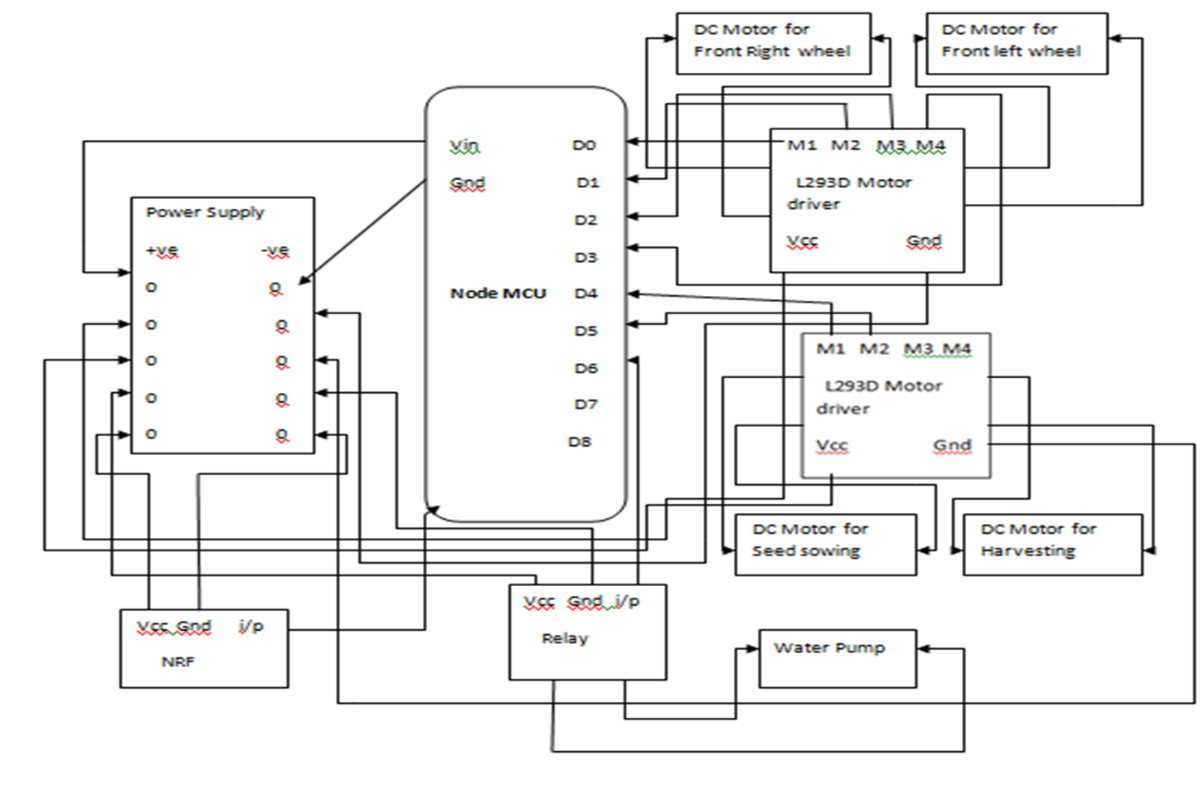
Figure.1 – Block Diagram of Master Robot
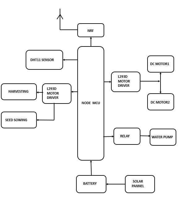
Figure.2 – Block Diagram of Slave Robot
MODELLING & ANALYSIS
HARDWARE REQUIREMENTS
DHT 11 SENSOR-
DHT11 is a low-cost digital sensor for sensing temperature and humidity. This sensor can be easily interfaced with any micro-controller such as Arduino, Raspberry Pi etc. to measure humidity and temperature instantaneously. DHT11 humidity and temperature sensor is available as a sensor and as a module. It is fairly simple to use, but requires careful timing to detect data. The only limitation on this sensor is you can only get new data from it once every 2 seconds.
.png)
Figure.3 – DHT 11 Sensor
L293D MOTOR DRIVER
A motor driver is an integrated circuit chip which is usually used to control motors in autonomous robots. ... These ICs are designed to control 2 DC motors simultaneously. L293D consist of two H-bridge. H-bridge is the simplest circuit for controlling a low current rated motor.
L293D IC is a typical Motor Driver IC which allows the DC motor to drive on any direction. This IC consists of 16-pins which are used to control a set of two DC motors instantaneously in any direction. It means, by using a L293D IC we can control two DC motors.
.png)
Figure.4 – L293D Motor Driver
RELAY
A 5v relay is an automatic switch that is commonly used in an automatic control circuit and to
control a high-current using a low-current signal. The input voltage of the relay signal ranges
from 0 to 5V.
The relay has two outputs-normally open and normally closed (NO and NC). ... Connecting a circuit or device between one of these two pins, the common pin on the relay output, and a power source will allow you to toggle power to a circuit or device.
.png)
Figure.5 – Relay
NODE MCU-
The NodeMCU (Node Microcontroller Unit) is an open-source software and hardware development environment that is built around a very inexpensive System-on-a-Chip (SoC) called the ESP8266. When purchased at bulk, the ESP8266 chip costs only $2 USD a piece. That makes it an excellent choice for IoT projects of all kinds.
The ESP8266 is a microcontroller with Wi-Fi capability. There are different modules and development boards with this system. NODEMCU is a development board with ESP8266 and a firmware with the same name. Similarly, the Arduino Uno is a microcontroller board based on 8-bit ATmega328P microcontroller.
.png)
Figure.6 – Node MCU
CLOUD
The cloud refers to software and services that run on the Internet, instead of locally on your computer. ... Some examples of cloud services include Google Drive, Apple iCloud, Netflix, Yahoo Mail, Dropbox and Microsoft One Drive.Examples would include: Dropbox, a file storage and sharing system. Microsoft Azure, which offers backup and disaster recovery services, hosting, and more. Rackspace, which offers data, security, and infrastructure services.
With the help of cloud, we can access any data, applications whenever and wherever we want to, over the internet. Cloud not only handles data storage remotely but it also protects and recovers all crashed or loss data, so we don't have to worry about crashed or loss of data, it gives you high security.
.png)
Figure.7 – CLOUD
NRF MODULE –
NRF24L01 is basically a wireless transceiver, which is used to send and receive data by using radio
waves. It is a single chip transceiver module. It uses SPI protocol for transmitting data. Its data
transmission speed is up to 2Mbps. NRF24L01 is normally used in industrial devices and projects for
data transmission.
.jpeg)
Figure.8 – NRF24L01 Module
BLYNK APPLICATION
The Blynk app is really an app editor. It allows you to create one or more projects. Each project can contain graphical widgets, like virtual LEDs, buttons, value displays and even a text terminal, and can interact with one or more devices.
SOFTWARE REQUIREMENTS
- Arduino IDE - Arduino UNO is a low-cost, flexible, and easy-to-use programmable open-source microcontroller board that can be integrated into a variety of electronic projects. This board can be interfaced with other Arduino boards, Arduino shields, Raspberry Pi boards and can control relays, LEDs, servos, and motors as an output.
- Blynk App - The Blynk app is really an app editor. It allows you to create one or more projects. Each project can contain graphical widgets, like virtual LEDs, buttons, value displays and even a text terminal, and can interact with one or more devices.
- RESULTS & DISCUSSIONS
The pin diagram consists of Node mcu microcontroller which is controller for the whole system as shown in fig. 1 & 2. A solar panel is connected to the battery for storing energy and further it is given to power supply charging circuitry which is providing +5 V for node mcu board and +12 V supply for driving DC motors using L298 motor driver module. NRF Module is connected with mode mcu and wirelessly with Android smartphone to control the whole system.
MASTER ROBOT
.png)
Figure.9 – Pin Diagram of Master Robot
.jpeg)
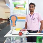
Figure.10 Prototype of Master Robot
SLAVE ROBOT
.png)
Figure.11 – Pin Diagram of Slave Robot
.jpeg)
Figure.12 Prototype of Master Robot
RESULTS AND DISCUSSIONS
The goal of the experiment is to prove the applicability of swarm robotics to precision farming. The application of swarm intelligence principles to agricultural robotics can lead to disruptive innovation, thanks to the parallel operation of multiple robots and their cooperation. The experiment aims at demonstrating such advantages and comparing them with the current state of the art within the context of a monitoring/mapping scenario.
4.1 SNAPSHOTS
MECHANISM
- Ploughing
The first and foremost step in the farming is ploughing. This process is done in order to loosen the soil and create a path or tracks on the farm land in order to sow the seeds uniformly. The structure and the design of the plough tool depends on the various constraints such as the type of soil to be ploughed and the depth required based on the type of crop that has to be grown and so on. There are many types of ploughing mechanisms that has been adopted which can be broadly classified into two categories; one is the manually driven ploughing tool and the other being machine driven. We have designed the plough tool using Catia software. The design and dimensions of the plough tool are in accordance with the size of the bots. The angle of inclination and length of the tool are calibrated by considering the depth required for ploughing the soil and it varies with the type of crops and soil. The tool is operated by using a 12V dc servomotor. The initial and final positions of the plough tool are controlled by coding it in a required manner.
.jpeg)
Figure.3.13 – Ploughing implementation
- Seeding
The next major step in the process of farming is seeding. Seeding usually depends on the type of crops being grown and the type of seeding varies over a variety of crops. In case of robots, utmost care has to be taken to ensure uniform spacing and controlled flow of the seeds from the bot; where in the seeds required for sowing is stored in a container and is mounted on the bot at the suitable position. The typical structure used for the seeding is as shown in the figure. controlled using the following mechanism as shown in the figure below. Pulses form MSP430 board is based on the frequency by which the seeds have to be sent. This is usually dependent on the speed if the Swarm bot or the nature of the seeds that has to be dispatched.
.jpeg)
Figure.3.14 – Seeding implementation
- Irrigation/ Fertilizer
Based on the amount of water required for that particular crop suitable irrigation methods are adopted. Our bot inculcates the drip irrigation for the irrigation process. The water required for the irrigation is stored in a container and is mounted onto the bot. The frequency of drop of the water is controlled using water pump. The water from the container flows to the field through the structure provided for irrigation uniformly. The same irrigation tool can be used for fertilizing by replacing the water with fertilizer.
.jpeg)
Figure.3.15 – Irrigation/ Fertilization Implementation
- Harvesting
The final process under farming is harvesting where in the crops are cut down or chopped using the designed harvesting tool. The harvesting tool is driven by the dc motor which rotates the harvesting tool at a rate of 1500rpm which is sufficient enough to cut down the crops in order to separate the grains from the crop. The present bot only performs the crop chopping action and doesn’t involve any process regarding the grain separation from the crop.
.jpeg)
Figure.3.16 – Harvesting support
ADVANTAGES, DISADVANTAGES AND APPLICATIONS
5.1 ADVANTAGES
- The three major criteria that drive our system are (1) Speed, (2) Accuracy, (3) Flexibility and (4) Low Cost.
- The systems mentioned above are either product specific or can handle equipment in only. Diversity in delivery systems has yet to be achieved and the system proposed in this paper completely satisfies all required multitasking capabilities and bridges the gap between the warehouse and the industrial activities.
- It drastically reduces the manpower thereby eliminating human error, thereby achieving maximum efficiency.
- Each robotic unit in the proposed system costs around $100 to $120. Therefore a complete system can be easily incorporated in a few thousands of dollars.
- It uses simple control software to control hundreds of autonomous mobile robots; this robotic fulfilment system enables extremely fast cycle times, from receiving to picking to shipping.
- The system is completely modular, which means you can start with a small system, and add more gear as your business grows.
- The size of the robots isn’t one of the constraints as it should possess enough mechanical power for heavy lifting.
- The result is a building that is quick and low-cost to set up, inexpensive to operate and easy to change anywhere in the world. Offers complete industrial delivery solution.
5.2 DISADVANTAGES
- Since it is a battery-operated robot, it’s performance is limited to certain period of time.
- High cost for master & slave robots
- Lack of technical knowledge in farmers since this system is operated using android phones.
5.3 APPLICATIONS
- The main aim of this Project is to Propose an IOT based Agribot and agriculture data acquisition using swarm robotics.
- This system gives an advance method to water and cut the crops with minimum man power.
- To measure temperature and humidity in the field and turn on the water pump.
- To cut down the weeds, harvest the field and sow the seeds.
CONCLUSION
Multipurpose farming robot has effectively actualized and tried for operations like ploughing, seeding, grass cutting and water sprinkling. An underlying result of this examination shows that the greater part of these frameworks that work with self-governing, are more adaptable than customary frameworks. The upsides of multipurpose horticultural robots are lessening human intercession, guaranteeing appropriate water system and proficient use of assets. In future, it can be reached out by utilizing ultrasonic sensors and cameras for playing out similar activities without human administrator for estimating the different parameters like soil condition, region secured by the robot and levelling.