
Introduction
Relays play an important role in automation circuits. Whether it's industrial or home, the type of relays can change but the principle remains the same. You may already know that relays in home automation are devices that activate another appliance. This might be anything from a light bulb to a motor. Smart home automation can be used in a variety of settings to improve the connectivity of your house. In other words, Smart Relays have installed devices that can be added to any electrical circuit and allow remote wireless control of anything else connected to that circuit. But what, if we make those smart relays IoT-friendly? Does this grab your attention? If yes, then read the entire article. Because in this tutorial, we are going to make a "Smart IoT Relay Module".
PCBWay commits to meeting the needs of its customers from different industries in terms of quality, delivery, cost-effectiveness, and any other demanding requests. As one of the most experienced PCB manufacturers in China. They pride themselves to be your best business partners as well as good friends in every aspect of your PCB needs.
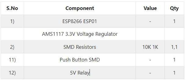
Hardware Required
Smart Relay Circuit

ESP8266-01 Code
#include <ESP8266WiFi.h>

const char* ssid = "Circuits DIY";
const char* password = "03433212601";
int RelayPin = 2; // GPIO2
WiFiServer server(80);

void setup()
{
Serial.begin(115200);
delay(10);
pinMode(RelayPin, OUTPUT);
digitalWrite(RelayPin, LOW);

// Connect to WiFi network

Serial.println();
Serial.println();
Serial.print("Connecting to ");
Serial.println(ssid);
WiFi.begin(ssid, password);

while (WiFi.status() != WL_CONNECTED) {
 delay(500);
 Serial.print(".");
 }
 Serial.println("");
 Serial.println("WiFi connected");
  // Start the server
  server.begin();
  Serial.println("Server started");
  // Print the IP address
  Serial.print("Use this URL to connect: ");
  Serial.print("http://");
  Serial.print(WiFi.localIP());
  Serial.println("/");
}

void loop() {

  // Check if a client has connected
  WiFiClient client = server.available();
  if (!client) {
    return;
  }

  // Wait until the client sends some data
  Serial.println("new client");
  while(!client.available()){
  delay(1);
  }

  // Read the first line of the request
  String request = client.readStringUntil('\r');
  Serial.println(request);
  client.flush();

  // Match the request
  int value = LOW;

  if (request.indexOf("/RELAY=ON") != -1)  {
    digitalWrite(RelayPin, LOW);
    value = LOW;
  }
  if (request.indexOf("/RELAY=OFF") != -1)  {
    digitalWrite(RelayPin, HIGH);
    value = HIGH;
  }

  // Return the response
  client.println("HTTP/1.1 200 OK");
  client.println("Content-Type: text/html");
  client.println(""); //  do not forget this one
  client.println("<!DOCTYPE HTML>");
  client.println("<html>");
  client.println("<h1>IoT Smart Relay</h1>");
  client.println("<h4>www.Circuits-DIY.com</h4>");
  client.println("<img src=\"https://static.thenounproject.com/png/731364-200.png\">");
  client.println("<br>");

  client.print("Relay Pin is now: ");
  if(value == LOW) {
    client.print("On");
  } else {
    client.print("Off");
  }
  client.println("<br><br>");
  client.println("<a href=\"/RELAY=ON\"\"><button>Turn On </button></a>");
  client.println("<a href=\"/RELAY=OFF\"\"><button>Turn Off </button></a><br />");
  client.println("</html>");
  delay(1);
  Serial.println("Client disonnected");
  Serial.println("");
}
Working Explanation
Here's the circuit's fundamental operating concept: Using a relay module and the application, we can turn on or off a bulb. After you make the connections properly, upload the code, and then open the Serial monitor. Next, simply copy and paste the provided IP into your phone's or system's browser. The application is now available for you to use.
Code Explanation
- First, we have included the libraries for the ESP8266 module. Then define our SSID and password. A char* is a char pointer. WiFiServer(80); This method establishes a server that waits for incoming connections on the given port. The default HTTP port is 80, and the web server is on port 80 here.
- In void setup, WiFi.begin establishes the network settings for the WiFi library and gives the status right away. WiFi.status() Return the connection status. WL_CONNECTED is assigned when connected to a WiFi network.
- we give the condition to quit early if any reading failed. WiFiClient client. creates a client that has the connection to a client-defined internet IP address.