
Introduction
A joule thief circuit enables the battery to light an LED in the circuit even if that LED requires more battery power. For example, a 1.85V led can be lightened by a 1.5V battery cell through this circuit. Hence, it allows the dead battery cells to drive the LED loads. In short, the joule thief circuit is the voltage booster circuit that transforms the input voltage into a greater periodic voltage value. However, the circuit does not boost current. Since it steals energy or joules that's why named joules their circuit. But this small circuit is also known as a joule ringer, blocking oscillator, and vampire torch.
The joule thief circuit can be made using different methods. We are going to build this circuit with two transistor methods. Thus, the circuit requires very cheap components including transistors, coil, capacitors, and LED as its main elements. Also, it's easy to handle and simple to create.
PCBWay commits to meeting the needs of its customers from different industries in terms of quality, delivery, cost-effectiveness, and any other demanding requests. As one of the most experienced PCB manufacturers in China. They pride themselves to be your best business partners as well as good friends in every aspect of your PCB needs.
Hardware Components
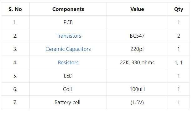
Joule Thief Circuit
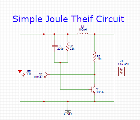
Working Explanation
The circuit operates by the 1.5V battery cells. A magnetic field developed around the coil because the current t passes through the wire's coil. As a result, it induces a greater amount of electricity in the coil, which is given to the base of transistor Q2 and opens the collector-emitter channel. The built-up energy of the circuit can't go through the transistor so it goes through the load, that is LED.