This project is only demonstrative and cannot be used in actual situations. This project can only, technically, identify line-to-ground problems. It doesn’t need AC power; it just uses DC power. A 5V relay is turned on and off by a digital pin on the Arduino, which regulates each of the aforementioned phases’ operation at a 5V level. Through the use of a resistor and a separate voltage source, the relay eventually prevents the circuit from being completed. The vertical line that represents the ground shortens horizontally with one of the phases when the switch is switched on. A filtered supply is sent to the Arduino’s ADC pin, and the programming may interpret the value as a distance. It is important to know that this project just follows the voltage division rule and does not follow any other principles.
This project is only demonstrative and cannot be used in actual situations. This project can only, technically, identify line-to-ground problems. It doesn’t need AC power; it just uses DC power. A 5V relay is turned on and off by a digital pin on the Arduino, which regulates each of the aforementioned phases’ operation at a 5V level. Through the use of a resistor and a separate voltage source, the relay eventually prevents the circuit from being completed. The vertical line that represents the ground shortens horizontally with one of the phases when the switch is switched on. A filtered supply is sent to the Arduino’s ADC pin, and the programming may interpret the value as a distance. It is important to know that this project just follows the voltage division rule and does not follow any other principles.
Circuit Connection
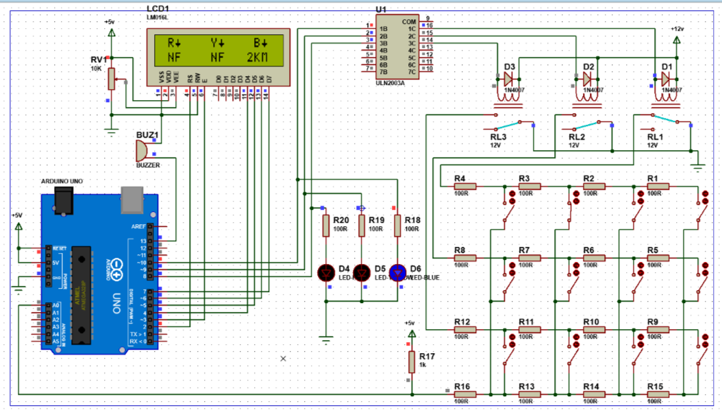
The Arduino code that is supplied is intended for a project that detects faults in underground cables. The code establishes pin connections for three relays (relay1, relay2, relay3), a buzzer, and an analog sensor (A0). It also uses the Liquid Crystal library to drive a 16×2 LCD display. The analog sensor reading and the computed distance are stored in two global variables, read_ADC and distance, respectively. An arrow-like custom symbol is made for the LCD display. Pin modes are configured and a custom LCD character is formed in the setup function. An introductory message appears on the LCD. The primary logic is continually carried out via the loop function. Sequential relay activation is done, and an LCD with arrows indicating the direction of the cable defect are displayed. The software computes the distance, reads data from the analog sensor, and shows the result on the LCD. In the event that a defect is found, the buzzer sounds momentarily. Three simulated cable portions are cycled through while the pattern repeats. The data function is in charge of reading the analog sensor, figuring out how far something is, and sounding the buzzer when a problem is found. Through the LCD and buzzer, the software simulates the identification of problems in various parts of an underground wire, offering both visible and aural feedback. The entire dependability of subterranean cable systems is increased by this approach, which makes it possible to evaluate cable sections for any problems in a methodical and sequential manner.
 Steps to Build:
Mount Components on Veroboard:
- Position Arduino UNO, 16×2 LCD Display, relays, diodes, ULN2003 IC, etc.
- Ensure proper placement for wiring.
Connect the LCD Display:
- Connect LCD pins to Arduino according to the code's configuration.
Set Up Relays and LEDs:
- Connect relays to Arduino digital pins (relay1 to pin 8, relay2 to pin 9, relay3 to pin 10).
- Connect red, yellow, and blue LEDs to appropriate digital pins.
Connect the Buzzer:
- Connect the buzzer to pin 13 of the Arduino.
Analog Sensor Connection:
- Connect the analog sensor (A0) to the Arduino.
Resistor Network:
- Set up with 100R resistors and switches for fault simulation at 100, 200, 300, and 400 ohms.
- Pull up the wire with a 1k ohm resistor and connect it to the Arduino's A0 pin.
Voltage Supply:
- Ensure a stable 12V supply using the 12V 2Amp power adapter.
Proteus Simulation:
Set Up Simulation:
- Use Proteus 8 to create a virtual simulation of the circuit.
- Add Arduino UNO, buzzer, 16×2 LCD, potentiometer, ULN2003 IC, relays, and LEDs.
Code Upload and Hex File:
- Write the Arduino code in the Arduino IDE.
- Compile the code and get the hex file address.
- Use this hex file in Proteus to run the simulation.
Simulation Testing:
- Ensure the simulation runs correctly, showing the welcome message and detecting faults in different phases.
Upload Arduino Code:
- Write the Code:
- Use the provided Arduino code.
- Upload Code:
- Connect the Arduino to your computer.
- Open the Arduino IDE, paste the code, and upload it to the Arduino UNO.
Testing and Calibration:
Connect and Test:
- Connect hardware components as per the circuit diagram.
- Power up the circuit and ensure all connections are secure.
Verify LCD Display:
- Check if the LCD displays the welcome message and changes according to the simulated faults.
Test Fault Detection:
- Simulate faults by adjusting the switches.
- Verify the distance displayed on the LCD and ensure the buzzer sounds as expected.
Adjust and Calibrate:
- If readings are not accurate, adjust the resistor values and connections.
- Ensure the Arduino correctly reads the sensor data and displays accurate fault distances.
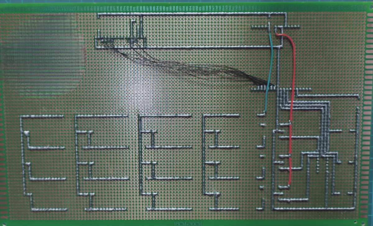
Final Outcome
![]()