AIM OF OUR PROJECT:
- The aim of this project is to decrease power consumption for delay sensitive and delay insensitive traffic.
- A fuzzy rule table is constructed with prediction of average inter arrival time of frame on the basis of outcome sleep time and power is evaluated.
- Proposed method offer effective power efficiency than previous inter arrival time method using Raspberry Pi.

EXISTING SYSTEM:
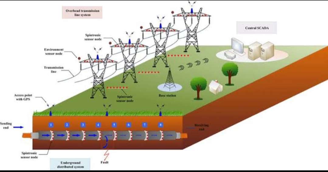
- In the existing system, the electric power infrastructure is highly vulnerable against many forms of natural and malicious physical events which can adversely affect the overall performance and stability of the grid.
- Although fault indicator technology has provided a reliable means to locate permanent faults, the technical crew and patrol teams still has to physically patrol and inspect the devices for longer hours to detect faulty sections of their transmission lines.
PROPOSED SYSTEM:
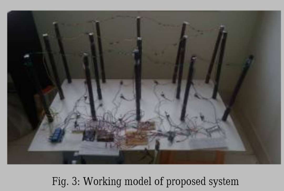
- In this Raspberry pi- a single board computer is used which programmed using the python, in this project the raspberry pi is connected to the unit consists of transformer, rectifier, filter and regulator.
- The AC voltage typically 230v RMS is connected to a transformer which steps that AC voltage down to the level of the desired AC voltage.
- This resulting DC voltage usually has some ripple or AC voltage variations.
- A regulator circuit can use this DC input to provide DC voltage that not only has much less ripple voltage but also remains the same DC value even the DC voltage varies somewhat, or the load connected to the output DC voltages changes.
- This system is connected to the server with a login page which has the online control system, Shutdown button if any shot circuit happens and log out button to come out of the system.
- This way IOT make the power efficiency and monitoring of the long lines.

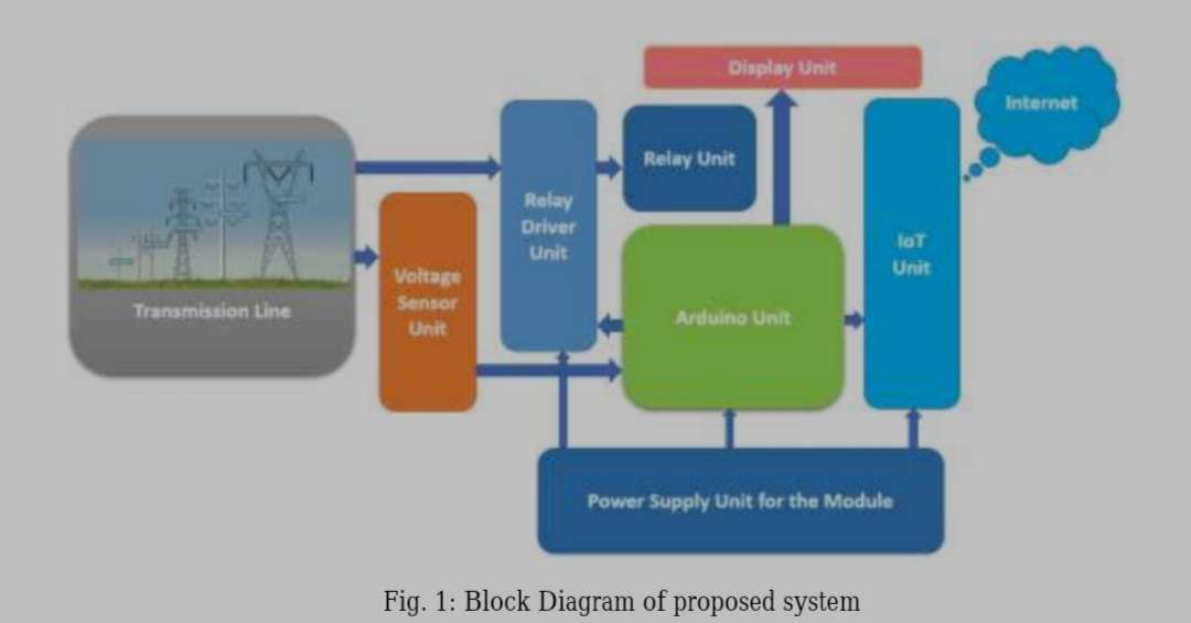
BLOCK DIAGRAM DESCRIPTION

- In this project Current transformer and Voltage transformer is used to know the changes in the current change and the voltage change.
- Similarly Transmission line will be connected with this sensor whose data will be uploaded to the web server.
- Connect to the Wi-Fi Technology with the server which can be accessed with the secure login page.
- Connect power supply for Raspberry pi
- Plug the HDMI cable in Raspberry pi from the monitor using VGA to HDMI converter cable
- Connect USB Mouse and USB keyboard to the Raspberry pi
HARDWARE REQUIREMENTS
- Raspberry Pi
- Current Transformer
- Voltage Transformer
- Transmission Line Node
- Relay Driver
- SD card
- Monitor
SOFTWARE REQUIREMENTS
- Raspbian Jessie
- HTML and PHP
- Language – Linux
- Python
CONCLUSION
According to this system, accuracy and automatic system for the transmission line is used using the IOT technology from where if there is any shot circuit automatically the system the change in voltage and current will be detected and automatically the system will indicate the problem. Using IOT technology Security login page is used to control and shut down the system.
REFERENCES
[1] “The establishment of an integrated automation production line with multiple monitoring and control loops” in 2018 IEEE International Conference on Applied System Invention (ICASI).
[2] “Power line communication in IoT-systems” in 2017 IEEE Conference of Russian Young Researchers in Electrical and Electronic Engineering (EIConRus).
