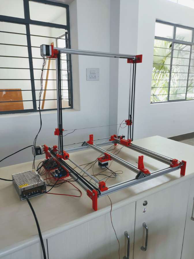


The base construction is made out of a 20x20mm aluminum profile because they are easy to use, we don’t have to drill any holes or something when assembling, and plus they are reusable. The motion of each axis is achieved by using linear bearings sliding on 8mm smooth rods. I used two rods for each axis. The sliding blocks are designed and 3D printed and for driving the sliding blocks, we are using NEMA 17 stepper motors. Then we put the linear bearing into 3D printed parts and insert them into the sliding rods and fix them in the aluminum profile as shown in the figure.

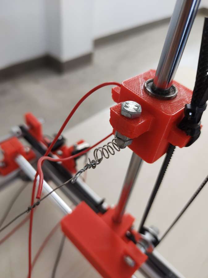
So next we need to install the resistance wire. This wire needs to be able to withstand high heat while maintaining uniform temperature across its length. That’s usually Nichrome wire or a stainless-steel fishing wire which is actually inexpensive and easy to get. In order to work properly, the wire needs to be tensioned between the two towers or sliding blocks. We attached M5 bolts on both sliding blocks and added small extension springs to them. Then we simply attached the wire to the springs. We tensioned the wire as much as the springs allowed. The wire needs to be tensioned like this with springs because when it will get hot it will also extend its length and so the springs will be able to compensate for that.
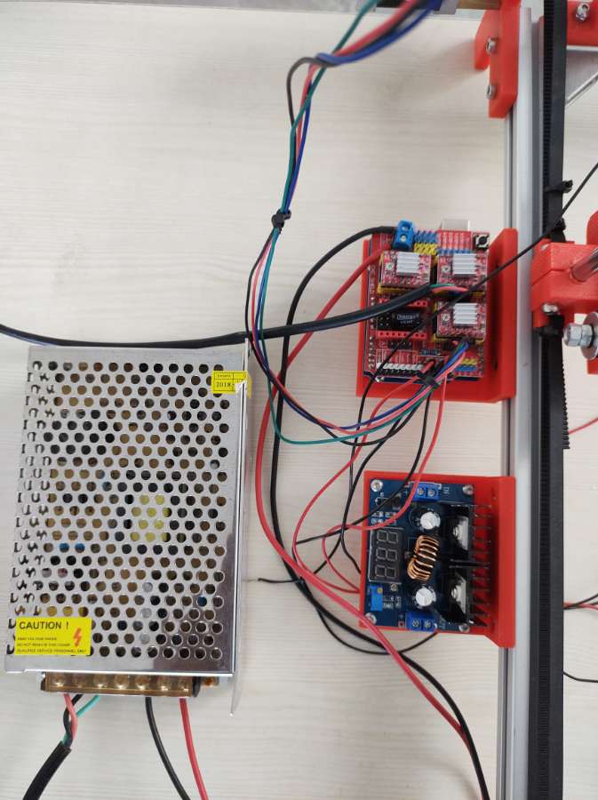
Then next we can connect the resistance wire with electrical wires. We will use DC power so the polarity doesn’t matter, it’s just important a current to flow through the wire in order to get hot. Here make sure your electrical wire is thick enough in order to support current draws of around 3 to 5 amps. Then we need to install the CNC shield and the buck converter and connect the cables of the stepper motors, Endstops, and the power supply to the nichrome wire from the buck converter as shown below.
Next, we need to upload a firmware to the Arduino which controls the motion of the machine. The most popular choice for DIY CNC machines is GRBL firmware. So, next we some kind of interface or a controller which will communicate and tell the Arduino what to do. For that purpose, we use a Universal G-code sender which is an open-source software to communicate with the Arduino to run the G-code of the respective design. Finally, we need to calibrate the steps of the motors in order to achieve correct and accurate movements. As we selected 16th step resolution on the drivers, and the motors have 200 physical steps, that means it will take 3200 steps in order for the motor to make full 360 degrees movement. Now depending on the transmission type, or in this case the size of the pulleys, we need to calculate the number of steps the motor needs so the machine moves 1mm. Next, we need to check whether the limit switches work properly. Then we need to correct the power supply of the nichrome to produce as much heat to cut the 15mm thick foam sheet. So, as we completed all the above-mentioned steps and finally we get our own automatic two axis foam cutting machine.