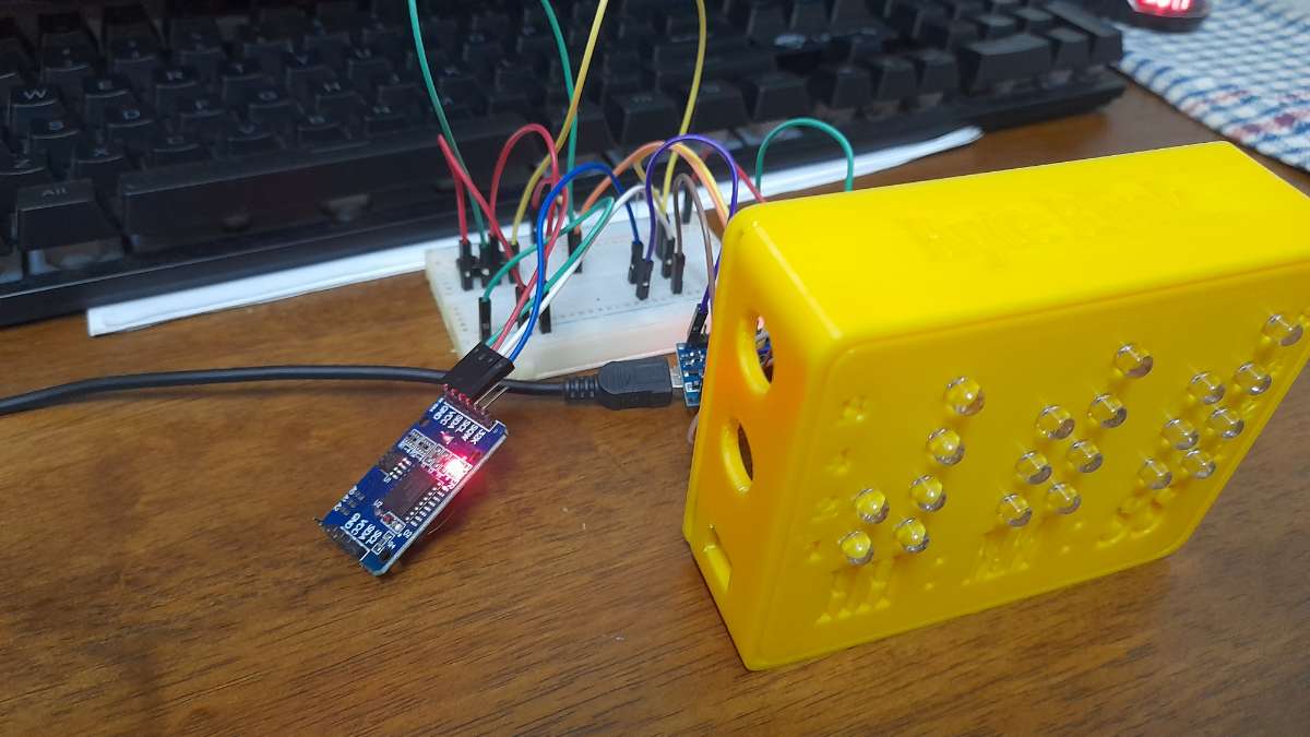
My project is a Binary Clock using LEDs in red, green, and blue, driven by an Arduino Nano and a DS3231 real-time clock module. The clock displays time in a 24-hour format with each LED representing a binary digit to indicate hours, minutes, and seconds. The combination of colours and binary representation creates a visually engaging and precise timekeeping device.
Demonstration Video:
THE MAKING PROCESS
1. Conceptualization and Design
Objective: Develop a binary clock that displays time using LEDs, controlled by an Arduino Nano and a DS1302 RTC module.
Innovative Aspects:
- Unique binary time display.
- Colour-coded LEDs for hours, minutes, and seconds (red, green, blue).
- Custom-designed 3D printed case for aesthetics and functionality.
2. Component Selection
Objective: Choose appropriate hardware components for the project.
Components used for this project are:
1. Arduino Nano microcontroller.
2. DS1302 RTC module for accurate timekeeping.
3. 20 LEDs (red, green, blue) for time display.
4. Resistors to limit current.
5. Two push buttons for user interaction (setting the time, etc.).
Innovative Aspects:
- Selection of high-quality, reliable components.
- Optimization of LED brightness and colour for clarity and appeal.
3. Circuit Design and Assembly
Objective: Design and assemble the electronic circuit.
Steps:
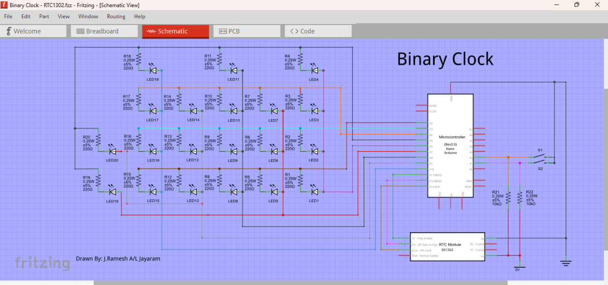
1. Schematic creation using Fritzing software.
2. Breadboard prototyping for testing.
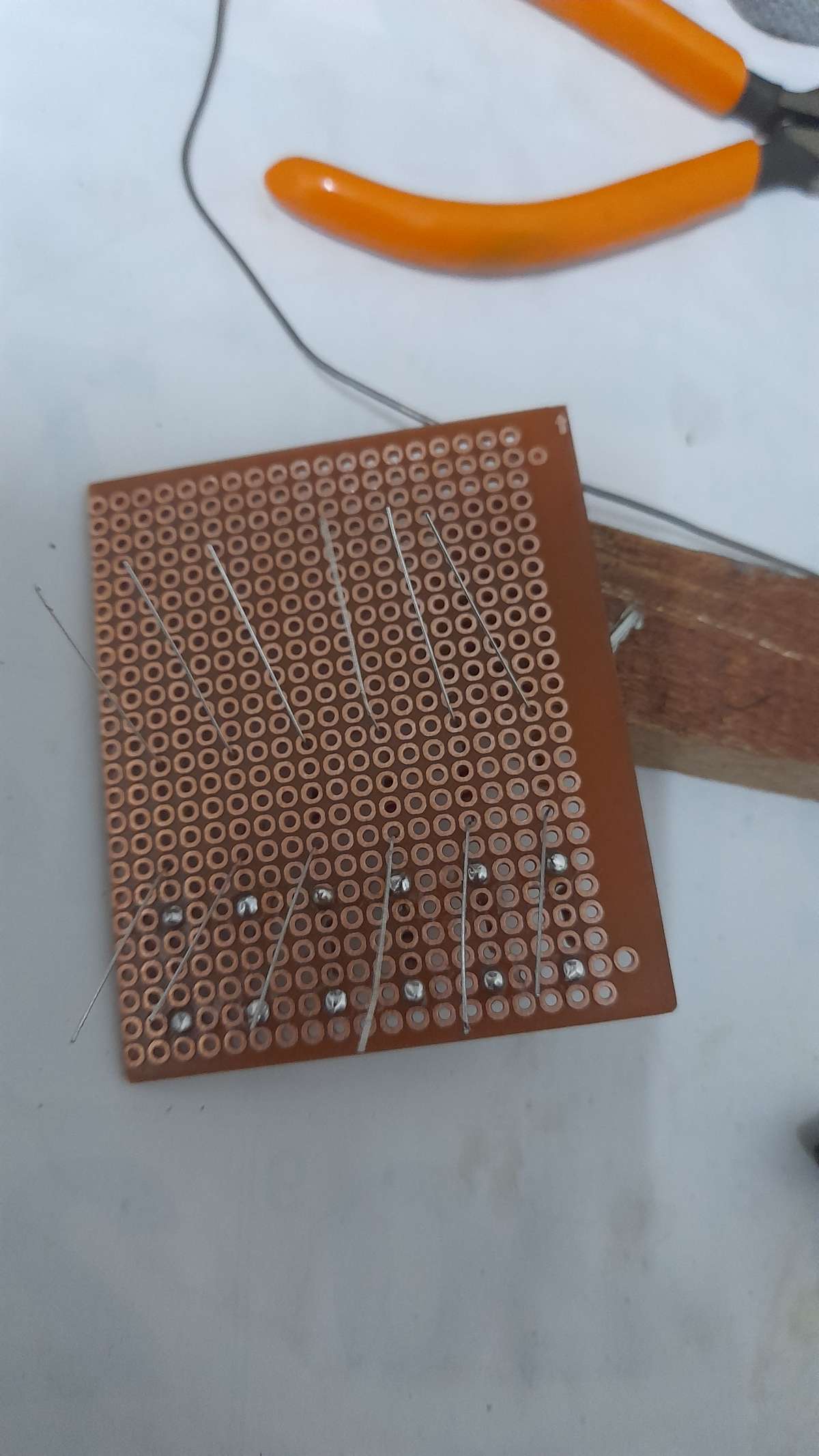
3. Soldering components onto a PCB for final assembly.
Innovative Aspects:
- Efficient circuit layout to minimize space and maximize performance.
- Integration of components to ensure stability and durability.
4. Programming
Objective: Develop the program to control the binary clock.
Steps:
1. Write and modify code for Arduino to read the time from the DS1302 module.
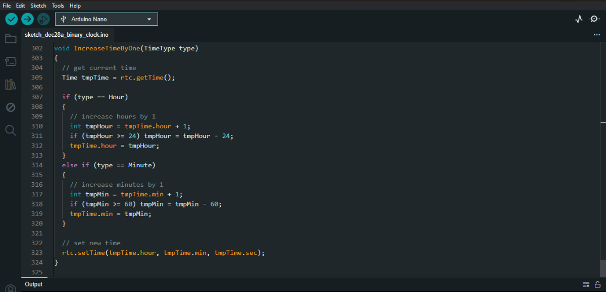
2. Convert time to binary format and control LEDs accordingly.
3. Implement button functionality for setting the time in 24 hours format.
Innovative Aspects:
- Optimized code for real-time performance.
- User-friendly interface and interaction.
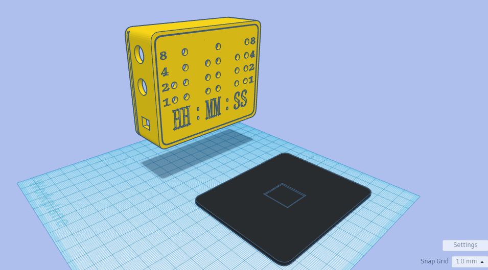
5. 3D Modelling and Printing
Objective: Design and print the clock’s case.
Steps:
1. Use Tinkercad to design the case, ensuring a precise fit for all components.
.png)
2. 3D print the case using suitable materials for durability and aesthetics.
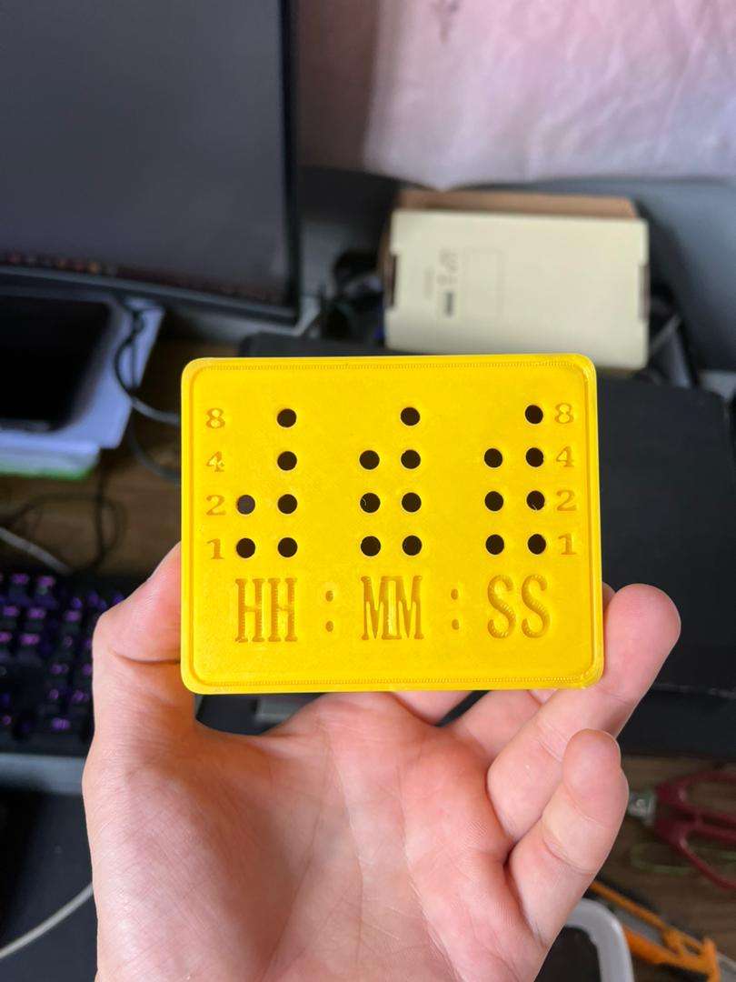
Innovative Aspects:
- Custom-designed case tailored to the project’s specific needs.
- Aesthetic design to enhance visual appeal and usability.
6. Testing and Calibration
Objective: Ensure the clock functions correctly and accurately.
Steps:
1. Test the binary clock in various conditions.
2. Calibrate the RTC module for precise timekeeping.