1. Introduction:
As days passed by the growth of technology would seem to be a major aspect bound to humans and machines. According to the present statics the wastage of water due to overflow of tanks has a major impact on the water scarcity.
In the present scenario of a busy world the manual monitoring of water filling in the tanks seems to have a difficulty in switching ON and OFF of the motor, due to which the wastage of water occurs.
There are a plenty of ways to prevent using the current technology yet they do not show a much impact over the prevention.
In this project, the Automatic Overflow Controller (AOC) is a high performance system, built compactly to provide basic features like auto / manual MODE selection soft switches, dry run protection, Overflow prevention and easy operation.
Suitable For Mono Block Pumps and Submersible Pumps.
Application Like Residential Buildings, apartment’s, Commercial Complexes, Hotels, Hospitals, . . . .Etc
Features like High reliability and Low maintenance because of Less circuit.
The circuit contains only the relay and the float switch as the main component.
No Microcontroller IC and No Programming
Visual Indications :
- Power ON indication
- Motor ON indication
- Tank full indication
- Sump Empty Indication
How It Works :
- Automatically starts the motor (turning on the MOTOR ON indication) when the water level in the over head tank drops below half of the tank and switches off the motor at tank full (Turning OFF the MOTOR ON indication and turning ON the TANK FULL indication)
- If the sump is empty, the motor goes OFF and the SUMP EMPTY indication turns ON.
Rocker Bypass Switch:
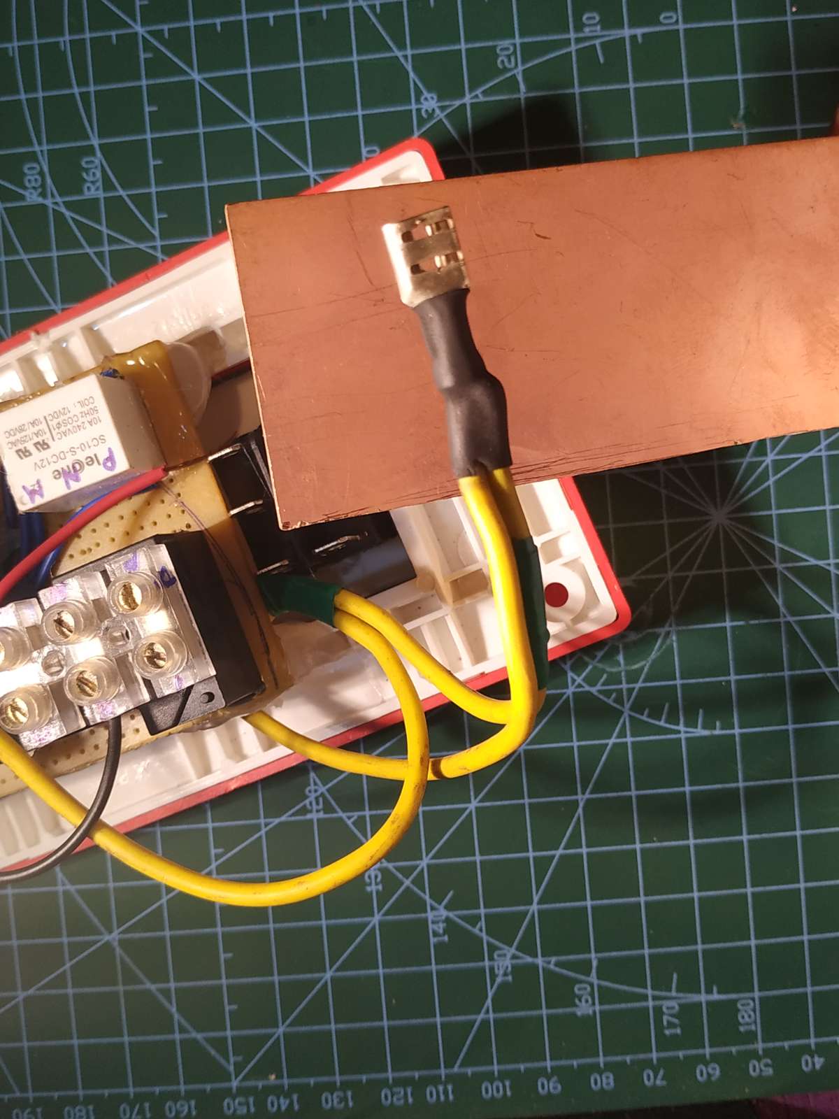
The optional rocker switch is provided to bypass system operation in case of system failure. so no need to disconnect the system when it gets failed.
Designed only for:
* Single phase motors.
*Upto 2HP motor.
*Requires external Starter to run a motor.
2.Designing the Circuit:
Since i don't have any PC or laptop i used my android mobile for circuit designing. The circuit was designed by the use of android application named Every Circuit (available in play store).
- For designing the circuit i have used Spst and Spdt switches instead of Float switch(refer the image for float switch wiring diagram)
- For simple understanding i have not used any AC sources and resistors
- Here i have used directly a 12v dc source and a dc motor for simulation purpose.
- In real time application, AC source, Resistors, Terminal connectors and Float switches need to be connected.
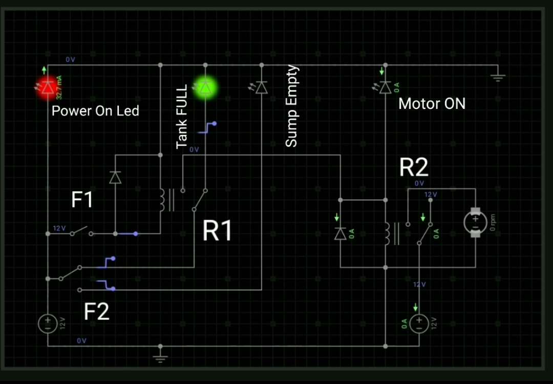
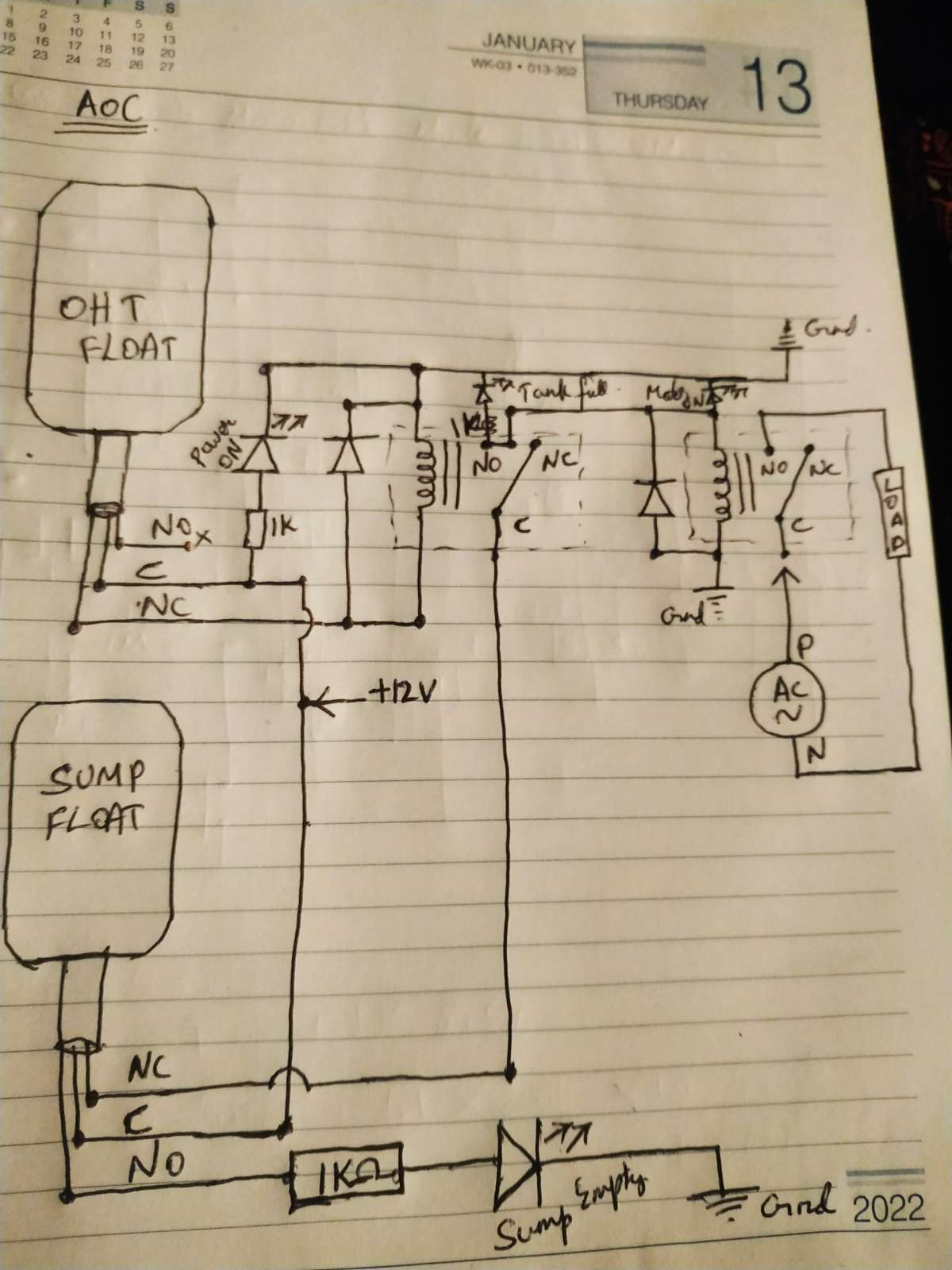
Explanation of circuit:
- 12v DC supply is given to the common terminal of both float switches and as well as to the power ON LED.
- NO terminal of the over head tank - float switch is connected to the coil of 10A relay.
- NO terminal of the Sump - float switch is connected to the common terminal of the 10A relay.
- NO terminal of the 10A relay is connected to the coil of 30A relay and Motor ON LED
- NC terminal of the 10A relay is connected to the Tank Full LED.
- NC terminal of the sump- float switch is connected to the Sump empty LED.
- NO terminal of the 30A relay goes to the input of Motor Starter box.
- Common terminal of the 30A relay is powerd up with 220V AC supply.
Working principle of the circuit:
Case 1: Over Head Tank is Empty and Sump is Full
- When the over head tank is empty, the float switch goes down and the coil of 10A relay is turned ON.
- Since the Sump tank is full, 12V supply flows from the Sump float to the common terminal of the 10A relay.
- Then the 10A relay triggers the 30A relay which leads to turn ON the Motor.
Case 2: Over Head tank is Full
- If the OHT is Full, the float switch float in upward direction and turns ON the Tank Full LED and turns the 10A relay OFF.
Case 3:
- If the sump is empty, the Motor does not run untill it is filled with water.
Refer the images and video for working of the circuit.
3.Assembling and soldering the circuit:
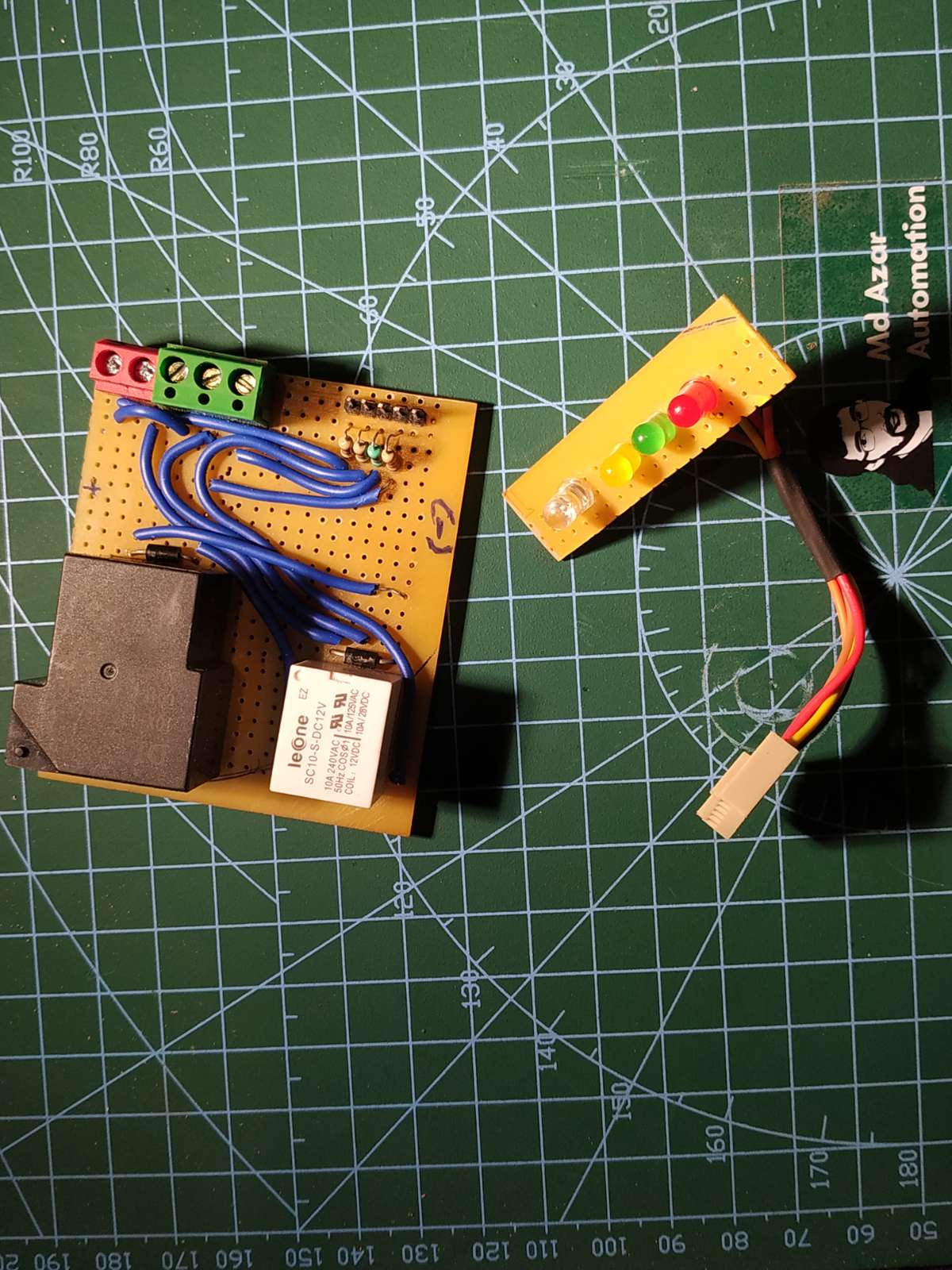
- Connections are made as per the circuit diagram.
- Terminal connectors are soldered for float switches.
- 4 x 1K resistors are connected in series with the Leds.
- 30A relay is used to withstand the large amount of current taken by the motor.
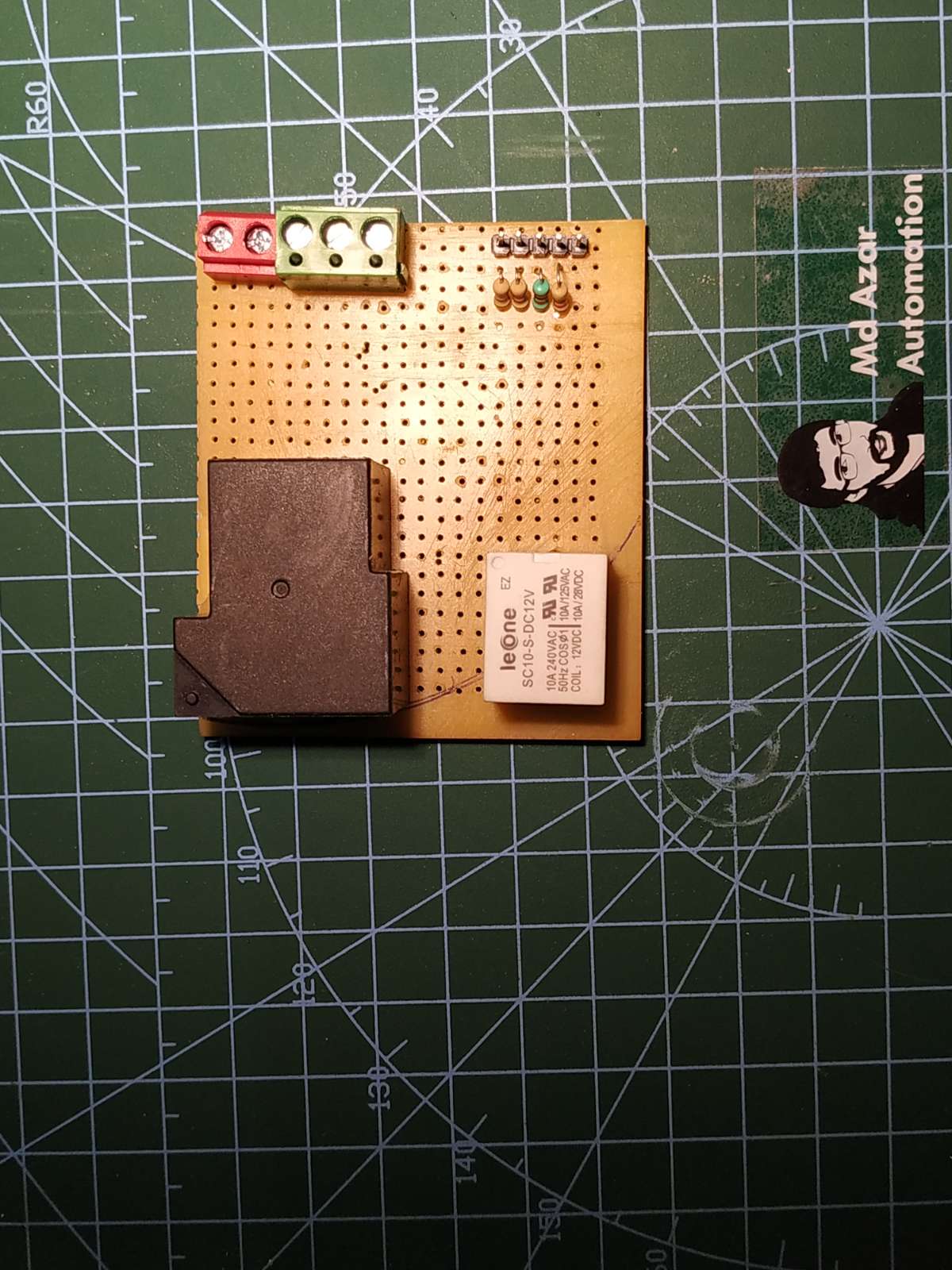
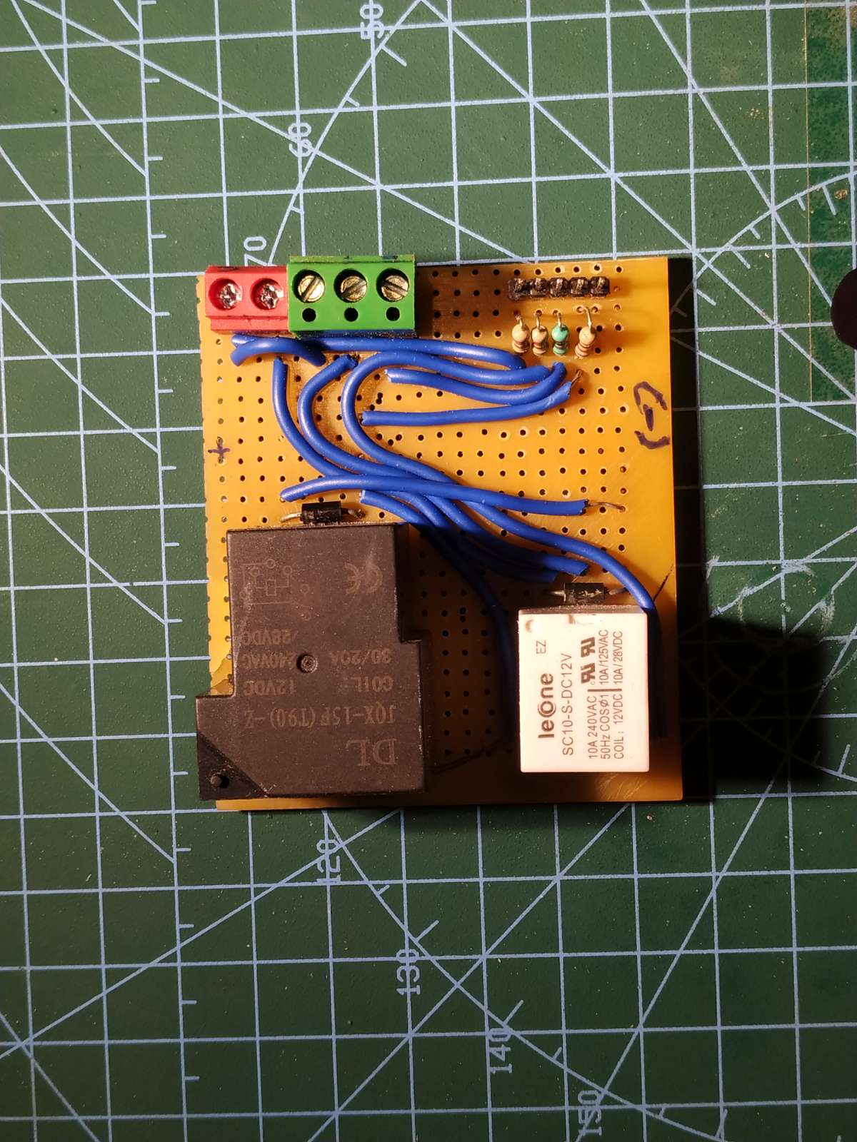
- 5pin Relimate connector is soldered for the connection of indication LEDs.
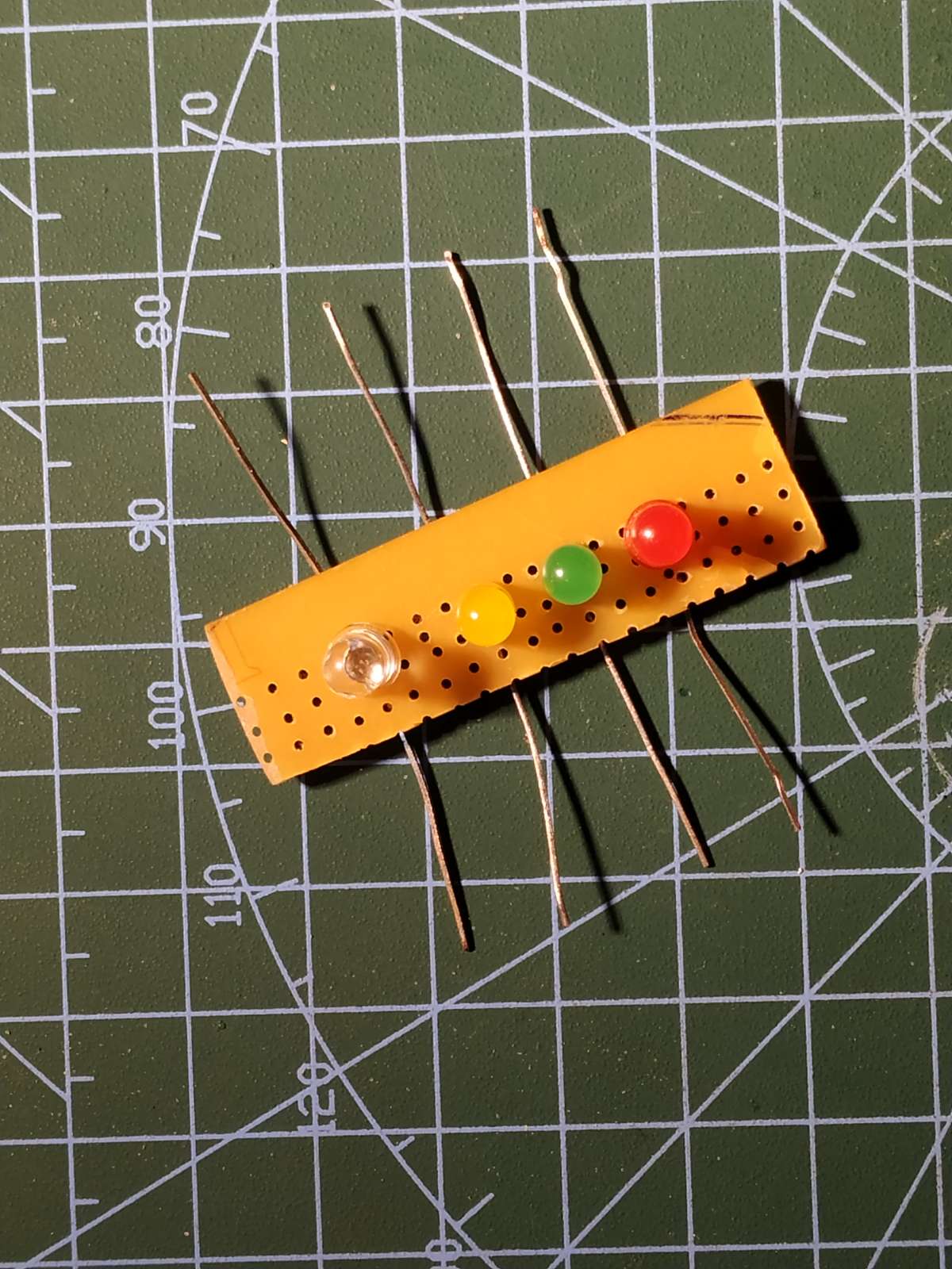
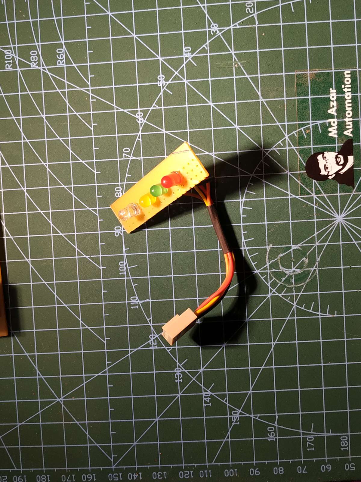
- Female terminal connector lugs are soldered with the 2.5 sq.mm wire, which will be connected to the DPTD bypass switch.
For more details, refer the Explanation of circuit in Step2
4.Testing the circuit:
*Confirm all the connections before turning ON the power supply*
*Don't play with high voltages*
For testing the circuit, i have used normal float switch and an AC bulb instead of Motor as shown in the video.
Whenever the sump is Empty, motor remains OFF.
If the OHT is Empty and sump is full, the motor turns ON.
5. Conclusion:
I hope you have liked this electronics project. I have shared all the required information for this project. I will really appreciate it if you share your valuable feedback.
Also if you have any query please write in the comment section. Thank you & Happy Learning...