INTRODUCTION
Light Fidelity (Li-Fi) is a fast, remote correspondence utilizing visible light. It falls under the classification of optical remote communications. Information transmission happens through Light Emitting Diode (LED) bulbs whose intensity changes (varies). During this variation in light intensity, communication takes places digitally. This innovation has huge applications where the utilization of Wi-Fi is restricted or prohibited. It likewise takes out the unfavorable wellbeing impacts of utilizing electromagnetic waves.
Except light is seen, information can't be hacked; thus, data transmission is secure. The utilization of light as a way to transmit information has been authored Li-Fi. The high speed innovation is like Wi-Fi but is quicker, enabling you to send and get more data in less time. By swapping glowing bulbs with LED’s which have electronic properties. Li-Fi could bring Internet access to more regions. It could reform the media communications industry.
OBJECTIVES
The main objectives of our proposed system are as follows:
- Design and development of embedded system to transmit data under the water using Li-Fi technology.
- The system is designed to transmit both text and audio signals.
HARDWARE IMPLEMENTATION
Introduction
In this chapter we are going to discuss about hardware implementation of the proposed Li-Fi technology based under water data transmission system. Fig. 3.1 shows the circuit diagram of transmitter section.
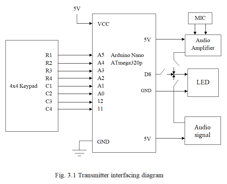
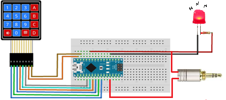
In this report in order to transmit data over Li-Fi, the text and voice signal are interfacing is shown in above diagram of our system, Fig 3.1 is the transmission circuit diagram, the circuit contains Arduino Nano which is operates with 5V/12V power supply. It also contains 4x4 Keypad, Audio Jack, MIC, Audio Amplifier, and output LED.
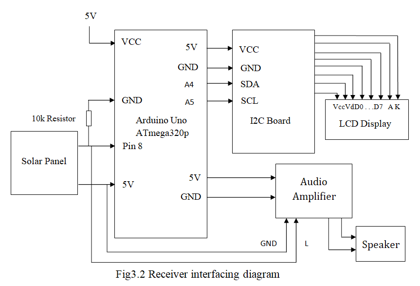
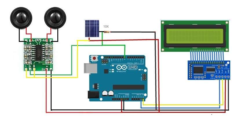
The above Fig 3.1 and 3.2 shows the interfacing diagram of our project system. It shows how all components are interfaced with Arduino Nano and Arduino UNO. The components are explained one by one below.
3.3 Connecting 4x4Keypad to Arduino Nano
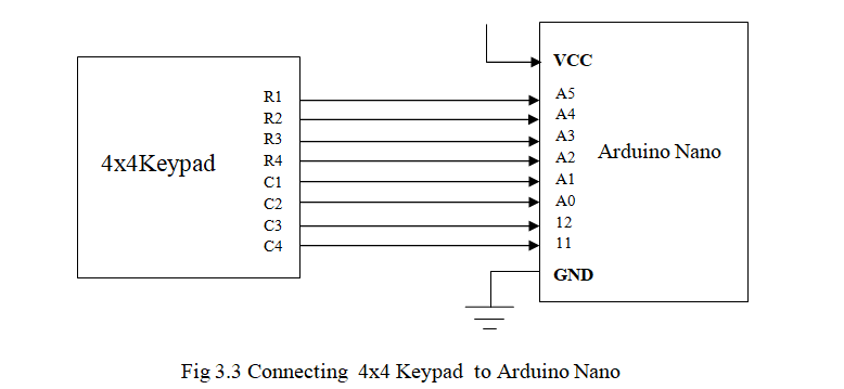
Keypad is connected to Arduino Nano as input , it has 4 rows and 4 columns which are R1,R2,R3.R4 And C1,C2,C3,C4 are connected to analog pins of Arduino Nano,VCC are connected to 5v, GND to ground.
3.4 Connecting LED to Arduino Nano
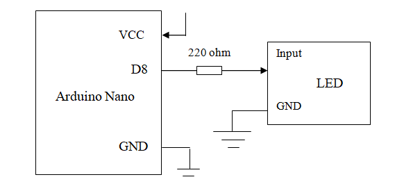
In our system LED is the main transmitter part or component, it has tow pins, GND to ground and pin to output pin (D8) with a resistor 220 ohm are connected to Arduino Nano.And VCC are connected to 5v, GND to ground.
3.5 Connecting Audio Signal to LED

In order to transmit voice data over Li-Fi, the voice signal is first amplified using the audio input3.5mm jack, is two pins one of that connected to 5V and another one is the output of LED to transmit the Audio Signals through the output LED, And LED connected GND to ground.
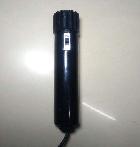
3.6 Connecting MIC to Audio amplifier circuit

In order to transmit voice data over Li-Fi, the voice signal is first amplified using the audio amplifier IC LM 386. The amplified voice signal is fed to LED for transmission. The circuit diagram used to amplify the voice signal is shown in Fig 3.6, The amplifier include IC LM386, which has 8 pins. The 1 and 8 pin connected in between capacitor 35vand1000µF pin 3 is connected to MIC positive terminal through capacitor 102k. 2 and 4 pins are shorted. The negative power supply given to pin 4, as well as pin 4 and 5 are the output of the amplifier. MIC positive end is connected to pin 6 through 10k ohm resistor, the positive power supply given to the pin 6. And negative terminal of the MIC is connected to negative power supply or GND.
3.7 Connecting Audio amplifier to LED
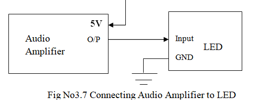
Amplifier input is two pins one of that connected to 5V and another one is the output of LED to transmit the Audio Signals through the output LED, And LED connected GND to ground.
3.8 Connecting Solar Panel to Arduino UNO
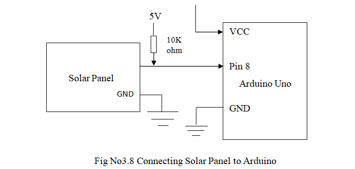
In receiver section solar panel is connected to pin 8 of Arduino UNO and also 5V with resistor 10k ohm and GND to ground. Arduino UNO board has VCC are connected to 5V, GND to ground.
3.9 Connecting LCD display to Arduino UNO

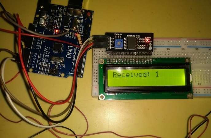
The LCD display is interface with the I2Cboard, It has 4 pins VCC are connected to 5v, GND to ground. On Arduino UNO board, SDA (data line) is on analog pin 4, and SCL (clock line) is on analog pin 5.
3.10 Connecting Solar Panel to Amplifier and Speaker
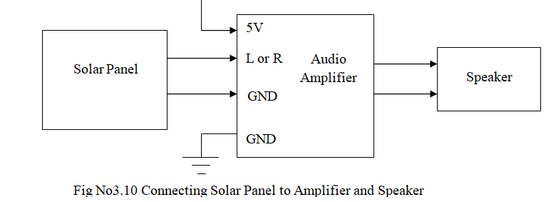
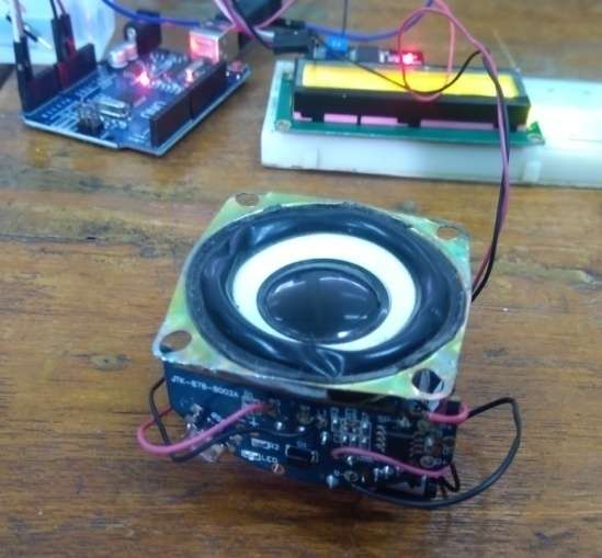
In receiver section the input solar panel is directly connected to the audio amplifier, the Amplifier is connected5V power supply and GND to ground. And the output pins are connected to the speaker.
SOFTWARE IMPLEMENTATION
4.1 Introduction
In this chapter we are going to discuss about software implementation and discussed the flow chart
4.2 Software Implementation
Software used: Arduino IDE tool
4.2.1 Arduino IDE tool
Arduino Integrated Development Environment is and official software which is introduced by Arduino.cc that is mainly used for writing, compiling and uploading the code in Arduino Device. Arduino IDE is an open source software, its easily available for operating systems like MAC, windows, Linux, and runs on JAVA platform that come with inbuilt functions and commands that helps for debugging, editing and compiling the code environment. Arduino UNO contains microcontroller on the board that is programmed and accepts code in form of codes/bits. Arduino IDE supports both C and C++ language. In our project we have used language C and programs written using Arduino software are called as sketches. Arduino IDE contains a text editor for writing code message area, text console, toolbar with buttons for command functions and series of menus.
How to create New Project
- Connect the Arduino to your computer's USB port
- set the board Arduino /Genuino Uno
- Select the serial port
- Select the File from the menu bar.
- Select New.
- After completion of coding save the file with the name
- verify and compile
- Upload
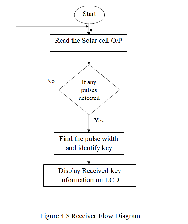
Flow Diagram
.png)
EXPERIMENTS AND RESULTS
5.1 Introduction
In this chapter we are going to discuss about the experiments and results of our proposed system. And also this chapter includes advantages, disadvantages, future scope, conclusion and bibliography of our project.
5.2 Experiments and Results
Our system helps to know proper crop details and avoid the Radio spectrum issues and disadvantages, to overcome that regarding issues. We will show our project result through demo. The pictures of each step are shown below.
Shown in the Fig. 5.1is our proposed system. It’s transmitting the text, navigation and audio signals through the LED in underwater.
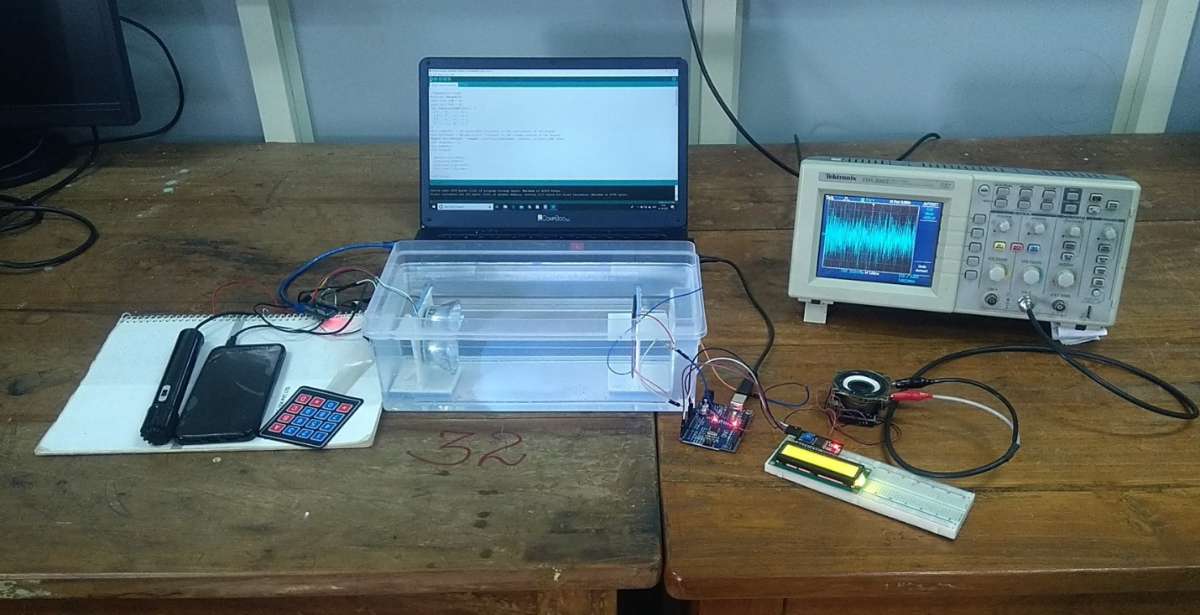
The external look of our model and the basic arrangements are shown in the figure 3.1 and 3.2
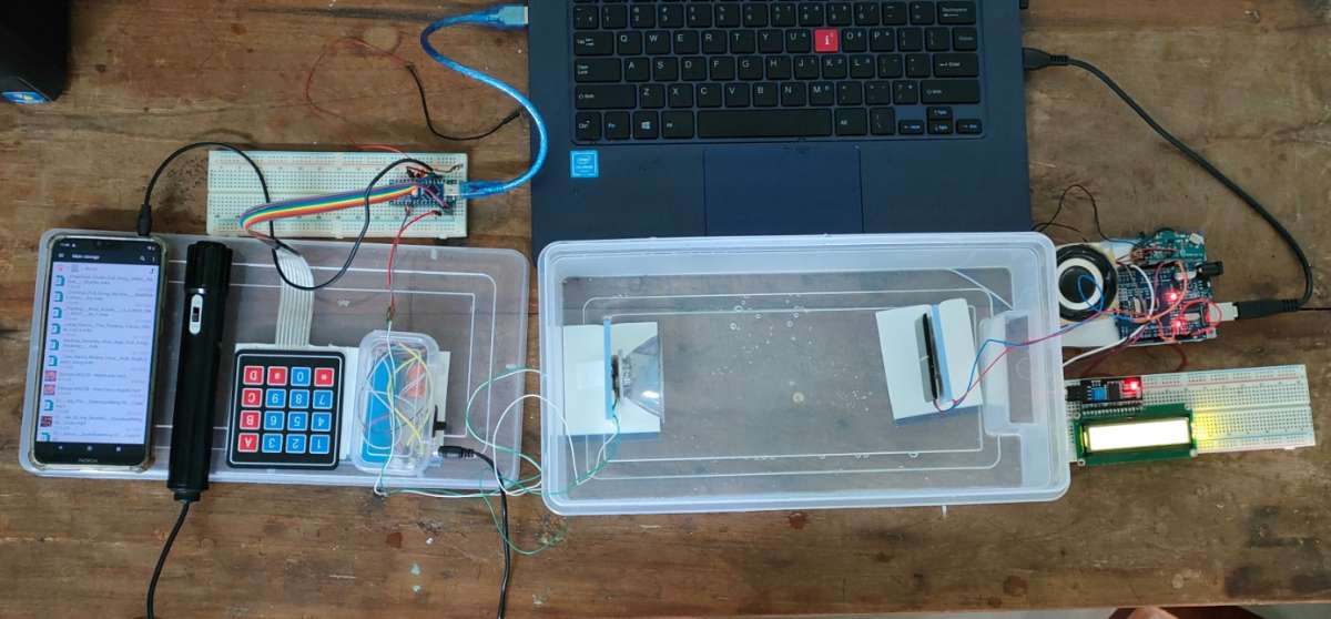
In above figure 5.2 shows when power is on or when we reset the system are shown on the display.

ADVANTAGES
Since Li-Fi uses light for data transmission, the problem of affecting marine animals due to SONAR technology can be avoided.
Li-Fi can be used to transmit data in underwater.
High efficiency compare
High security
No license needed.
Lighting points can be used as data transmitting hotspot.
The issues of the shortage of radio frequency bandwidth may be shorted out by Li-Fi.
DISADVANTAGES
Light can’t pass through objects.
A major challenge facing Li-Fi is how the receiving device will transmit back to transmitter.
Other sources of light may interfere with the signal.
It doesn’t work in the bright areas.
Future Scope
For the secured data transmission, the data can be encrypted and transmitted.
The light intensity can be amplified for the longer distance data transmission.
This technology can be used to make every LED bulb into a Li-Fi hotspot to transmit data wirelessly.
Conclusion
In this project, explanation on the design and working of the designed system to transmit data under the water based on Li-Fi technology is explained. The system is capable of transmitting text data to indicate the navigation direction, voice data and the audio data. The designed system is working satisfactorily.