There are two major application of this product
- Vehicle Engine monitoring
- Traffic signal integration with the vehicle for violation detection.
Traffic signal violations, traffic rules violations like over speed, wrong turns, and braking traffic signals cause inefficient traffic control and sometimes accidents. In practice, there is not any mechanism installed for detecting traffic signal violations, so some people break the rule as there is no check on them, many time which causes accidents, even some time people loses their life.
The system is designed in order to ensure traffic management efficient, adaptive traffic signal controls, and vehicle safety. The system mounted on the mobile vehicle has an RF transmitter and receiver unit, GPS, digital compass, altimeter which gives the position and heading of the vehicle.
Vehicle Engine Monitoring
The various evolving technologies are providing crucial information to the fleet operators, for instance, on-board diagnostics version II (OBD II) supports self-diagnostics and reporting capabilities. Fuel efficiency means the efficiency of a process that converts chemical energy contained in a fuel into kinetic energy or work. In the case of transport, fuel economy is the ratio of the distance traversed per unit of fuel consumed. Generally, it is called the mileage of the vehicle. The energy consumption in India is the fourth largest after China, the USA, & Russia Due to this we have to pay huge foreign exchange.
The eco-driving skill has been getting more and more attention because of global warming and increasing oil prices. So far, existing eco-driving assistance systems mainly offered raw instantaneous fuel economy to drivers. So, increasing fuel efficiency is a very crucial thing for us. The rising fuel price and maintenance costs, concerns about driver and passenger safety are, especially challenging tasks. But with the advancement of new technology, these challenging tasks can be handle in an optimized way. The proposed project deals with these issues and gives us efficient engine utilization, and also providing driving assistance in these areas.
.png)
We are proposing an intelligent system that will be capable of providing driver assistance, engine utilization, and eco-driving feature. The vehicle consists of many microcontrollers and sensor circuitry that give various status signals such as fuel level, engine speed, rpm, etc. This data is available to us at the OBD terminal. OBD is having self-diagnostics and reporting capabilities. The OBD II is the latest version of OBD, it communicates to the host computer via CAN protocol.
The ELM 327 IC is used for converting a CAN, KWP 2000, ISO 9141-2, J1850 PWM, and J1850 VPWM protocol into RS-232 protocol. Mostly, after 2008 CAN is the more popular protocol. The ELM IC is used to make serial communication possible on a microcontroller. As many microcontrollers are not able to communicate directly on the CAN protocol. So, this IC is useful for making communication compatible within the system. For selecting a microcontroller our basic needs are microcontroller should have at least four UARTs and one SPI port capability. Also, it should be compatible with IoT applications. All these features are available in the ARM Cortex M series microcontroller.
The GPS gives the latitude and longitude details. Thus we are able to track the vehicle on a smartphone app. The GPS information is extracted from the GPS receiver and by converting it to proper form we can upload the latitude and longitude details on google maps. The forgiving the exact location of the vehicle we need at least four satellites.
We are going to do decision-making according to throttle position, speed of the vehicle, load-carrying capacity, and gear levels. Analysis of these parameters gives various information which will be required for us to assist a driver to improve his driver performance. The information will be transferred through an IoT. The IoT is the latest technology we are proposing in this method. The data is processed by cloud/server and we will give this input to the driver through a GPRS or Bluetooth. The driver having an on-board Graphical LCD or it may have his own Smartphone. Through this device, the system will be able to provide an assistant to the driver.
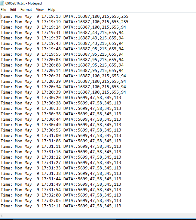
In this proposed system we are also providing SD card support. Which also gives better connectivity. Suppose there are some radio range connectivity issues faced by the GSM module. In that case, we can store the data in SD card meanwhile and when radio range is available we can transfer this data to the Cloud/Server.
We are proposing a Smartphone app in this method which will assist the driver in each point. The smartphone app will show the status of fuel level, coolant temp, fuel efficiency, and speed in rpm. The Cloud/Server also detects any harsh driving or sharp cornering if any. It will give these details to the driver and warn him about his driving. The information provided by Cloud/Server to the app is in real-time. By these data, one can change his driving style and improve his performance. In this way, we can achieve efficient engine utilization and eco-driving.
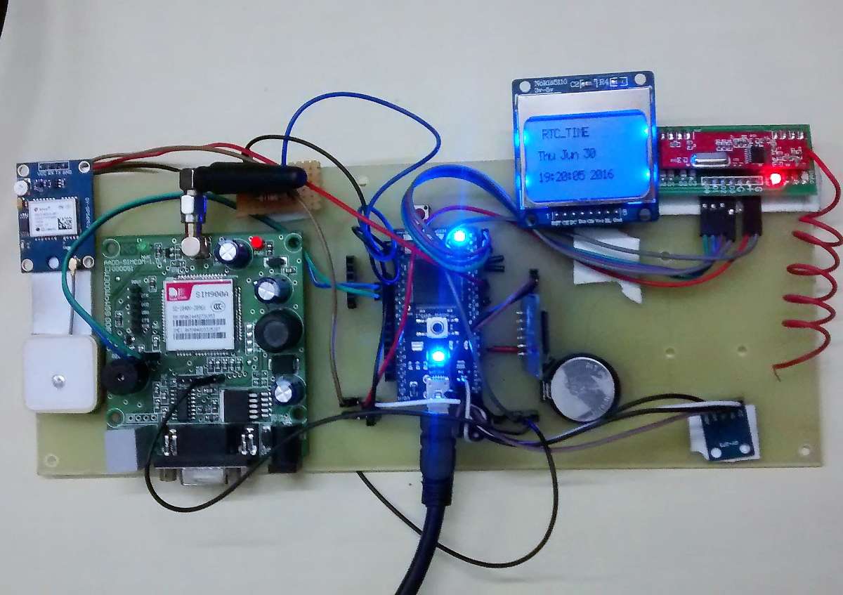
.png)
Modes of OBD II
.png)
.png)
Pin Description:
1 Vendor Option
2 J1850 Bus +
3 Vendor Option
4 Chassis Ground
5 Signal Ground
6 CAN (J-2234) High
7 ISO 9141-2 K-Line
8 Vendor Option
9 Vendor Option
10 J1850 Bus -
11 Vendor Option
12 Vendor Option
13 Vendor Option
14 CAN (J-2234) Low
15 ISO 9141-2 L-Line
16 Battery Power
Communicating with the ELM 327 :
To communicate ELM directly you will firstly need HyperTerminal Software. There is various HyperTerminal software available. I am using TeraTerm. Firstly you have to make sure the baud rate is selected at 38400 because it is the default baud rate for OBD to make communication with Personal Computer. Otherwise, you will not see any results and garbage value will be displayed on HyperTerminal. Please set your connection for 8 data bits, no parity bits, and 1 stop bit, and set it for the proper 'line end' mode. All of the response from ELM327 is terminated with a single carriage return character and optionally, a linefeed character.
Properly connected ELM 327 will glow its four LED outputs in sequence (as a lamp test) and will then send the message :
ELM327 v1.5
>
This is proper output from ELM with the prompt character " > ". The ELM version displayed may be varied according to ELM used. The command for the rest of the ELM is ATZ and ATI. These AT commands are not case-sensitive. you can type it using small letters too.
AT command Summary
.png)
.png)
.png)
.png)
Pin Connection
MBED ---------> ELM327 IC
P1 (GND) ----> GND
P28(Tx) ------> Tx
P27(Rx) ------> Rx
MBED ---------> GSM Module
P1 (GND) ----> GND
P9(Tx) ------> Tx
P10(Rx) ------> Rx
Nokia 5110 LCD Display
.png)
MBED ---------> NOKIA 5110 LCD
P11 (MOSI) ---> MOSI
P12 (MISO) -----> MISO
P13 (SCLK) -----> SCLK
P15 ---------------> CS
P16 -----------------> RST
P17------------------> DC
VCC -----------------> VCC
GND -----------------> GND
SD card
.png)
MBED ------------> SD card module
P5(MOSI) -------> MOSI
P6(MISO)--------> MISO
P7(SCLK)--------> SCLK
P8-------------------> CS
VCC----------------> VCC
GND----------------> GND
Bluetooth HC-05
.png)
MBED ----------> Bluetooth HC-05 module
NC ---------------> KEY
VCC--------------> VCC
GND--------------> GND
P19---------------> TX
P20---------------> RX
NC----------------> STATE
GPS Module
.png)
MBED-----------> GPS Module
RX----------------> TX
VCC-------------> VCC
GND------------> GND
with this, the RF communication module is interfaced with the Controller to receive traffic signal codes, which is explained in the next part.
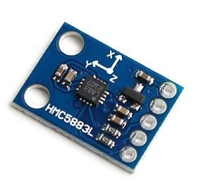
Digital Compass (HMC5883L) is used for getting the heading direction of the vehicle, the combination of the digital compass and traffic signal codes are explained in the next part.
Firmware Development
ObdSimWindows Simulation Software
For testing OBDII commands and working of the firmware, ObdSIM can be used in the lab for the convince in the development, with this Mbed.org or Keil can be used as IDE.
.png)
.png)
Testing with the vehicle: (RPM Test)
.png)
Connections
.jpg)
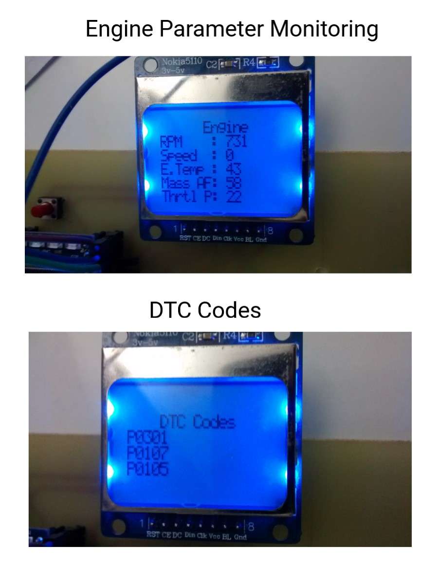
Display Output
Results on ThingSpeak
.png)
.png)
SD Card Data
Traffic management and violation detection
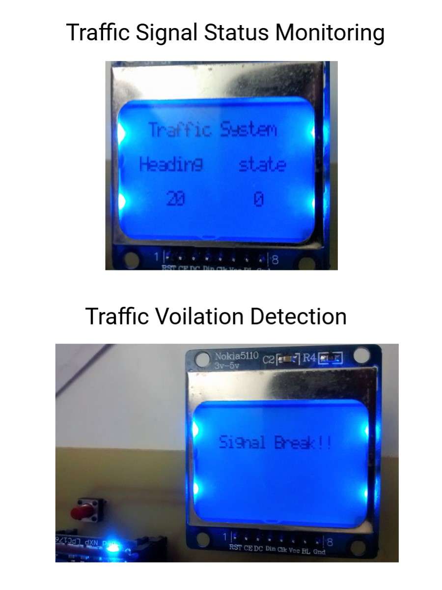
At each traffic signal, installed system broadcast signal state and position of center 1 of the signal within a certain area, all vehicle-mounted device in that area receives the signal irrespective of a vehicle heading angle direction. The device in the vehicle analyses the received signal’s center position containing GPS coordinates, altitude, and signal state. After comparing state, position, and altitude, the system detects whether the signal is applicable or not for the current vehicle, on which it is mounted, if it is applicable and the state is GREEN for a vehicle heading direction, then the device shows a green signal on display. If for current heading direction signal is RED, and the vehicle is in a predefined crossing area near to the signal center point 1, the system gives warning in form of visual, vibration, audio. after a certain time, if the vehicle speed is not slowed down or the vehicle doesn’t stop, the system will show traffic signal violation and sends a traffic signal violation report including position and vehicle information to the local traffic management authority server using GPRS or any data connection from Subscriber Identity Module.
In the case of flyovers, double-decker flyover traffic signals, the vehicle-mounted devices will receive signals from different altitudes traffic signals. From received signal state vehicle-mounted device always compares the position including altitude. If there is a significant difference in altitude, vehicle-mounted device ignore that signal state, vehicle-mounted device will only respond to signals states from the same altitude
level with a certain margin, so the system will work in case of flyovers without any irrelevant signal state issues.
The system also receives traffic warnings like speed limits, one-way indicators. Installed traffic warning transmitter with certain distance intervals, which transmit speed limit value with a range in form distance. If the vehicle crosses the speed limit value, the system will give a warning and after a certain time if speed does not get under the defined speed limit, the system will show traffic rule violation and sends traffic rule violation report including position and
vehicle information to the local traffic management authority server using GPRS or any data connection from the subscriber identity module.
When the vehicle comes in a broadcasting range of traffic signal, the vehicle-mounted device starts sending vehicle position and vehicle identification number to the system installed at a traffic signal with everyone second-time interval. Vehicle position includes GPS coordinates, heading of the vehicle, and altitude, so the system installed at traffic signal analyses the total count of moving vehicles from different directions. By comparing the counts with different states of the signals, the time of each signal state will get changed to make more efficient use of the traffic signal state. Adaptive traffic signal states will keep always updating with analyzing the count of vehicles from different directions.
The vehicle-mounted device system also monitors the exhaust gas, if it is crossed the predefined level, it shows the warning, after a certain time interval if the exhaust gas level not under the expected level, the system sends a report to the server. Also, the system has the ability to send Diagnostic trouble codes from OBD-II to a predefined server of the service provider. The system also shows the seat belt warning depending on the seat occupied.
In case of accidents, airbag activation, or extreme cases detected by using gyro sensors and accelerometer sensors, the system sends emergency SMS to the predefined numbers by Subscriber Identity Module.
The system uses a storage device for backup in case of GPRS, data connectivity unavailability, once the GPRS, data connectivity establishes, it starts sending report, data to respective servers of local traffic authority, service provider, or other defined server.
System structure
The system mounted on the mobile vehicle has an RF transmitter and receiver unit, GPS, digital compass, altimeter which gives the position and heading of the vehicle. At each traffic signal, installed system broadcast signal state and position of center 1 of the signal within a certain area, all vehicle-mounted device in that area receives the signal irrespective of the vehicle heading angle direction. The device in the vehicle analyses the received signal’s center position containing GPS coordinates, altitude, and signal state. After comparing state, position, and altitude, the system detects whether the signal is applicable or not for the current vehicle, on which it is mounted, if it is applicable and the state is GREEN for a vehicle heading direction, then the device shows a green signal on display. If for current heading direction signal is RED, and the vehicle is in a predefined crossing area near to the signal center point 1, the system gives warning in form of visual, vibration, audio. after a certain time if the vehicle speed is not slowed down or the vehicle doesn’t stop, the system will show traffic signal violation and sends a traffic signal violation report including position and vehicle information to the local traffic management authority server using GPRS or any data connection from Subscriber Identity Module.

The figure covers the various signal states from all possible vehicle heading directions. All possible vehicle heading directions is divided into 16 equal parts of heading angle. Depending on the signal type and angle of the vehicle heading (considering North as zero degrees), each state with angle has a unique code assigned, which will be broadcasted. A vehicle heading angle 24 indicates the direction of a vehicle heading with an angle of 45` degree. Heading angle 25 covers from 0 degrees to 360 degrees of angle. Signal state with type and angle has code assigned 26, 27, 28 accordingly for each direction of heading and each type of signal. Each signal state is assigned to heading angle considering +-12 degree of angle margin. i.e. code assigned for a vehicle heading angle 0` degree, is assigned with +-12-degree angle margin, from 348 degrees to 12 degrees.
A. Signal Types
- Signal Type1: This signal type is defined as a free signal, which means at this state green signal will be allowed for heading left, right, straight, and taking U-turn in the proper allowed direction.
- Signal Type2: This state will be green for two directions opposite to each other, allowed direction vehicle can head toward the front direction and left allowed direction. Heading to the right or U-turn will not be allowed.
- Signal Type3: This state will be green for two directions opposite to each other. Heading towards the front will be allowed only.
B. Signal State Code
- ST100: This is signal state 26, specifies signal type 1 traffic signal, which is a GREEN signal for a vehicle having a heading angle of 348 degrees to 12 degrees. Each heading has an angle margin +-12` degree. Vehicle in this particular heading can head towards the right, left straight, or also can take a U-turn in this signal state.
- ST106: Similarly, a signal state in signal type 1 indicates a GREEN signal for a vehicle heading angle 147` degree to 123` degree.
- ST200: This signal state specifies a signal in type 2 traffic signal, which is a GREEN signal for a vehicle having a heading angle 348 degrees to 12 degrees i.e. angle margin +-12` degree to 0` degree. This signal is also GREEN for opposite direction heading vehicle, angle 180 with +- 12` angle margin. Vehicles in this particular heading can head towards left and straight only, vehicles are not allowed to take U-turn or right turn in this signal state. if in this particular angle heading vehicle takes right turn or U-turn, it will be a traffic violation and the system will warn this violation before reporting.
- ST204: This signal state in signal type 2 indicates GREEN signal for a vehicle heading angle 90 with +- 12 degree of angle margin, also it will be GREEN for a vehicle heading angle 270` degree with +-12-degree angle margin.
- ST300: This signal state specifies a signal in type 3 traffic signal, which is a GREEN signal for a vehicle having a heading angle 348 degrees to 12 degrees i.e. angle margin +-12` degree to 0` degree. This signal is also GREEN for opposite direction heading vehicle, angle 180 with +- 12` angle margin. Vehicles in this particular heading can head straight only, vehicles are not allowed to take U-turn, left turn, and right turn in this signal state. if in this particular angle heading vehicle takes a right turn, left turn, or U-turn, it will be a traffic violation and the system will warn of this violation before reporting.
- ST304: signal state in signal type 2 indicates GREEN signal for a vehicle heading angle 90 with +-12 degree of angle margin, also it will be GREEN for a vehicle heading angle 270` degree with +-12-degree angle margin.
Vehicle direction based count
Adaptive Traffic Management, which will be achieved by the counts of vehicles coming from different directions, using multiple frequency channels and code allocation CDMA systems, at receiving end receiver able to receive transmitted signals from vehicles. The received signal will be like this:
- Vehicle ID number(VIN)
- GPS coordinates, speed
- Heading angle
At the receiver end, there is an algorithm, when it receives the data, it compares vehicle number with the existing vehicle in the count, and if it is a new vehicle in that particular area, it increments the count according to the heading angle for that vehicle. In the case of the flyover, it also considers the altitude of the vehicle. So once the receiver has the count based in a different direction, 2nd algorithm, does the signal adaptive calculations. Depending on previous counts, weightage Ws are calculated. Ws for each direction of the street, e.g. Ws1, Ws2.Ws3, Ws4, etc
Depending on each weightage factor signal timing gets varied adaptively until and unless weightage do not become equal. So depending on the count of vehicle and weightage signal timing factor always compensate accordingly.
- Applying algorithm for the real world
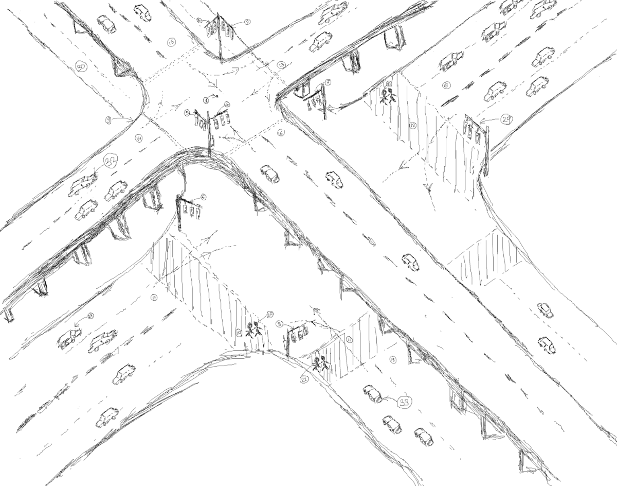
The system at the traffic light pole broadcasts traffic signal state code, traffic signal position i.e. GPS coordinates, and altitude of the traffic signal pole. In that particular area traveling, System mounted on the vehicle receives the signal state and position of that particular traffic pole center point 1. Depending on the altitude and position of the received signal state, the system mounted on the vehicle will detect whether it is an applicable traffic signal to that particular vehicle. If the received signal state is from the same altitude level, the system calculates the distance from the moving vehicle to the traffic center point, according to the distance it gives the notifications to the driver, in case of RED traffic signal system start showing a warning, if the vehicle crosses the particular distance limit, system report it as a traffic violation.
In the case of flyover signal states which are broadcasted and received by a system mounted on a vehicle traveling under the flyover, this system compares received signal state position, altitude and current vehicle position, altitude. As there is a significant difference in altitude, the vehicle-mounted system ignores such received signals from different altitudes.
In case of street signal states under the flyover broadcasted and received by system mounted on the vehicle on the flyover, will compare current vehicle position and traffic signal state position, as there is a significant difference in altitude, a system in vehicle ignore it.
This drawing is for illustrating the system working in the situation of flyover above the street with both having the traffic signals with different states and types.
Flyover 9 over the street has four directions for a vehicle heading 13,14,15,16. Flyover way 13,14 has angled for heading vehicle 225 degrees and 45 degrees respectively. The traffic light for the indication is 2 for flyover street 13 and 5 for flyover street 14. Another flyover way 15,16 has angled for heading vehicles 315 degrees and 135 degrees respectively. The traffic light for the indication is 3 for flyover street 15 and 4 for flyover street 16.
Below the flyover, there is also a street that has four directions for a vehicle heading 17,18,19. street 17,19 has angled for heading vehicle 45 degrees and 225 degrees respectively. The traffic light for the indication is 6 for street 17 and 29 for street 19. Another street 18,30 has angled for heading vehicles 135 degrees and 315 degrees respectively. The traffic light for the indication is 8 for street 18 and 31 for street 30.
Flyover signal broadcasting system and street signal broadcasting system, broadcast the signals twice a second, with time-multiplexed manner.
Broadcasted signal from traffic pole= <traffic signal state>+ <GPS coordinates of the center junction of street >+ <Altitude>
Assuming flyover has a traffic signal state ST102 which is a GREEN signal for a vehicle heading with the angle of 45 degrees with a +-12-degree margin. signal broadcasted on flyover will include ST102, longitude, latitude, altitude. When the system on vehicle 32 receives the broadcasted signal, it compares it with the vehicle current position and altitude, as altitude is in marginal range, so the system will check vehicle 32 heading angle and vehicle GPS coordinates. As algorithm defined, the system will start warning when the vehicle comes near center 1 with a particular distance limit. If vehicle 32 crosses this distance limit, it will be reported as traffic signal violations.
Assuming ground street has a traffic signal state ST106 which is GREEN signal for a vehicle heading with angle 135 degrees with +-12-degree margin. signal broadcasted on street will include ST106, longitude, latitude, altitude. When the system on vehicle 33 receives the broadcasted signal, it compares it with the vehicle current position and altitude, as altitude is in marginal range, so the system will check vehicle 33 heading angle and vehicle GPS coordinates. As algorithm defined, the system will start warning when the vehicle comes near center 34 with a particular distance limit. If vehicle 33 crosses this distance limit, it will be reported as traffic signal violations.
When vehicle 33 receives a broadcasted signal from the flyover signal, which includes traffic signal state ST102 with latitude, longitude, and altitude of the central junction point of that traffic signal. An algorithm compares the vehicle 33 position, there is a significant difference in altitude, so the system on the vehicle will ignore this received signal.
Another aspect of this system is Adaptive traffic signal
Transmitted signal from vehicle= [Vehicle identity Number+ vehicle GPS coordinates + altitude + heading angle]
The transmitter transmits on different frequency bands, receiver with frequency division multiple access with wider frequency band and lower range communication used. The system at a traffic signal has an algorithm code to count mobile vehicles heading in a different direction. Depending on the count from different heading proportional time of GREEN signal updates at every cycle of the signal.

Traffic warnings such as speed limit will be broadcasted as traffic warning with heading angles, system on vehicle receives this traffic warning if the vehicle is over speed, the system starts showing the warning. After a certain time, if speed is not at the limit, a traffic rule violation reported by that vehicle name.
In case of One-way allowed heading angles are transmitted, which will be received by system mounted on the vehicle, if the vehicle is not heading towards the allowed angle, the system has the ability to detect it and give warning as above defined. The system has the ability to detect the number of occupied seats and the status of seat belts also Exhaust gas emission level and giving warning or reporting in case of violations.
Algorithm and system use
This algorithm with the system can be used for vehicle traffic violations and adaptive traffic signal management with all types of street combinations. This system efficiently manages the traffic violation detection with the highest accuracy of another camera-based system [1] and an IR-based system [2]. Adaptive traffic signals can adjust signal timing and will help to improve traffic management efficiency. So this system can keep watch on traffic violations with better efficiency.