.jpg)
Introducing PulseSync: Your Gateway to Advanced Telemedicine. PulseSync heralds a new era in telemedicine, seamlessly blending state-of-the-art technology with the utmost in medical innovation. This groundbreaking device offers a comprehensive suite of health monitoring capabilities, all integrated into a single, user-friendly platform. Designed to empower both healthcare professionals and patients, Pulse Sync represents the pinnacle of accessible, accurate, and proactive healthcare delivery.
At its core, PulseSync harnesses the power of Artificial Intelligence (AI) to deliver real-time health assessments across four critical domains. Firstly, leveraging a digital stethoscope coupled with AI algorithms, it accurately analyzes heart sounds to detect a spectrum of diseases within trained classes. From identifying murmurs to irregular rhythms, Pulse Sync offers unparalleled insight into cardiac health, enabling early detection and proactive intervention.
Additionally, PulseSync integrates a pulse-oximeter sensor, enabling precise measurement of heart rate and blood oxygen levels. Whether monitoring vital signs during remote consultations or tracking fluctuations in oxygen saturation, this functionality ensures comprehensive cardiovascular assessment with clinical-grade accuracy.
Furthermore, the device incorporates a non-contact thermal sensor for seamless temperature measurement. With a simple scan, users can obtain precise body temperature readings, facilitating rapid fever detection and monitoring of systemic health indicators.
Central to the Pulse Sync experience is its companion app, developed using the Arduino IoT Cloud dashboard. This intuitive platform provides seamless access to all data, enabling healthcare providers to review and analyze patient metrics in real-time. From trend analysis to remote consultation capabilities, the app serves as a comprehensive tool for personalized healthcare management.
Features
- AI-Powered Heart Sound Analysis
- Pulse-Oximeter SensorFor Heart Rate and Blood Oxygen Level Measurements
- Non-contact thermal SensorForBody Temperature Measurement
- Companion AppForVisualisation And Remote Monitoring
- Open-Source Design
Hardware
XIAO ESP32 S3


The XIAO ESP32 S3 microcontroller is at the heart of our innovative health device, providing robust processing power and versatile connectivity options. Here's a closer look at why we chose this microcontroller for our project:
- Powerful Processor: The XIAO ESP32 S3 features a powerful dual-core Xtensa LX7 CPU, offering clock speeds up to 240 MHz. This enables efficient real-time processing of health data, ensuring rapid and accurate results.
- Integrated Wi-Fi and Bluetooth Connectivity: With built-in Wi-Fi and Bluetooth connectivity, the ESP32 S3 enables seamless data transmission to external devices such as smartphones or cloud servers. This allows users to conveniently monitor their health metrics remotely and share data with healthcare professionals.
- Rich Peripheral Support: The microcontroller provides a wide range of peripherals, including SPI, I2C,I2S, UART, and ADC interfaces, facilitating seamless integration with various sensors and components.
- Low Power Consumption: Despite its high processing capabilities, the ESP32 S3 is designed for low power consumption, making it suitable for battery-operated applications such as our portable health device. This ensures prolonged usage without frequent recharging.
- Compact Size: The XIAO ESP32 S3 is renowned for its compact form factor, making it an ideal choice for space-constrained applications such as our portable health device. Despite its small size, this microcontroller packs a punch with its robust processing power, ensuring efficient operation without compromising performance
- Direct LiPo Battery Connection: One notable feature of the ESP32 S3 is its ability to connect directly to a LiPo (Lithium Polymer) battery. This eliminates the need for additional voltage regulation circuitry, simplifying the device's power management system and reducing overall complexity. The direct LiPo battery connection enhances the device's portability and convenience, allowing users to easily recharge or replace the battery as needed.
Sensors
Our health device incorporates cutting-edge sensors to provide comprehensive health monitoring capabilities. Here are the key sensors utilized in our project:
1. MLX90614 Non-Contact Temperature Sensor:

The MLX90614 sensor enables hygienic and swift body temperature monitoring through non-contact measurements. By harnessing infrared thermopile technology, it provides precise temperature readings without requiring direct skin contact, enhancing user comfort and convenience. With a standard accuracy of ±0.5˚C around room temperatures, and a medical-grade variant boasting an impressive ±0.2˚C accuracy within a limited temperature range around the human body temperature, the MLX90614 ensures reliable temperature assessment. Utilizing the I2C communication protocol, it seamlessly interacts with the microcontroller for efficient data exchange.
2. MAX30102 Pulse Oximeter Sensor:

The MAX30102 sensor plays a pivotal role in measuring the oxygen saturation (SPO2) levels in the patient's blood, offering essential insights into respiratory health. Through the emission and detection of light at precise wavelengths, this sensor accurately calculates SPO2 levels, facilitating early detection of potential respiratory issues. Additionally, by leveraging the I2C communication protocol, the MAX30102 seamlessly interfaces with the microcontroller, ensuring efficient data transmission and processing.
3. PDM Microphone

In our health device, the INMP441 MEMS High Precision Omnidirectional Microphone Module serves a vital role in detecting irregularities in heartbeat rhythms. It operates by utilizing high-precision audio capture technology and MEMS (Micro-Electro-Mechanical Systems) technology, which integrates miniaturized mechanical components to capture sound waves with exceptional sensitivity and fidelity. This enables the precise detection of subtle sound variations, essential for identifying potential heart issues.
The module's omnidirectional sensing pattern ensures it can capture sounds from all directions with equal sensitivity, enhancing the reliability of heartbeat irregularity detection regardless of the microphone's orientation relative to the patient's chest.
Communication between the INMP441 microphone module and the XIAO ESP32 S3 microcontroller is facilitated through the I2S (Inter-IC Sound) protocol. In the I2S protocol:
- Data Transmission: Audio data is transmitted serially in two separate channels: the left channel (L) and the right channel (R). Each channel consists of a data line (SD), a clock line (SCK), and a word select line (WS).
- Clock Synchronization: The SCK line carries the clock signal, synchronizing the transmission of audio data between the microphone module and the microcontroller to ensure accurate timing and reliable data transfer.
- Word Select Line: The WS line indicates the beginning of each audio data frame, distinguishing between left and right channel data, serving as a synchronization signal for the microcontroller to decode the incoming audio data stream.
- Data Line: The SD line carries the digital audio data stream encoded in pulse density modulation (PDM) format, a modulation technique used to represent analog signals in a digital format, suitable for high-fidelity audio transmission.
By leveraging the INMP441 MEMS microphone module and the I2S communication protocol, our health device accurately captures cardiac sounds and detects irregular heartbeat patterns. This, coupled with machine learning algorithms running on the XIAO ESP32 S3 microcontroller via Edge Impulse, enables early detection of cardiac abnormalities, empowering users to take proactive measures for their heart health.
4. 0.96 inch OLED & Push Button Module

The icons displayed on our device's screen are powered by the 0.96-inch OLED display. We strategically utilize specific portions of the display to enhance the device's aesthetic appeal. It communicates with the controller via I2C.

For changing the measuring mode, we've incorporated a small push-button module. This compact button allows users to switch between different measurement modes with ease, ensuring seamless interaction with the device.
Design

The device design was crafted using Fusion 360 and then materialized using PLA filament with a 20% infill.

Assembly

First, we always do our prototype on the breadboard. After finalising the module we put it in the enclosure. We have used the Ido surgical stethoscope to capture the heartbeat.

First, we attached the PDM mic to the stethoscope by removing the unwanted portion.

Then we started attaching the remaining components. Here is the schematic for the connection.


 A 400mAh LiPo battery is used to power the device. This battery has a nominal voltage of 3.7 volts and can output a maximum voltage of 4.2 volts when fully charged.

Here is our final device.

Software
Connecting PulseSync to Arduino Cloud
Arduino Cloud offers compatibility with an extensive array of ESP32/ESP8266-based development boards. Renowned for their versatility in IoT projects, ESP chips are easily programmable using the Arduino language (C++).
Configuring ESP-based boards within the Arduino Cloud is swift and straightforward. This involves generating a Device ID and Secret Key, which, along with your Wi-Fi® credentials, provide ample information for a seamless connection to the Arduino Cloud.
These are the steps required to link your ESP32 board with the Arduino Cloud. Before proceeding, ensure you possess a registered Arduino account and have access to the Arduino Cloud platform.
1. Configure The Device
First, navigate to Arduino Cloud - Devices. Here you can see all your devices, and configure a new one.
Click on "Add Device"

Select "Third Party Device"
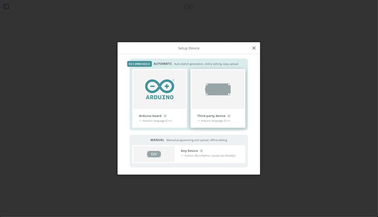
Choose your board from the list (in our case ESP32S3 Dev Board)
Name your board, e.g. ESP32
Save your Device ID and Secret Key. This will be used to connect to the Arduino Cloud.
2. Configure Thing
Then, proceed to the Things tab. Here, you'll see a list of your Things alongside a button to initiate the creation of a new one. By generating a new Thing, you will open up a new configuration space.
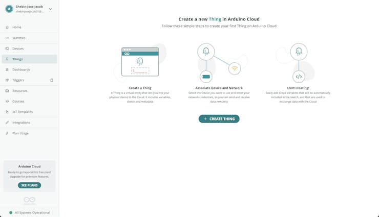
A "Thing" serves as a digital counterpart to your hardware, where variables are established for synchronization between the Cloud and the board. Modifications made within this space will automatically propagate to a generated sketch.
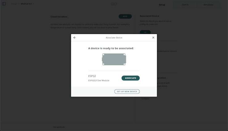
1. Initially, let's connect the desired device by selecting the "Select Device" button located within the "Associated Devices" section to the right.

2. No we can create variables. Let's start with an Integer variable that will store the heart rate.
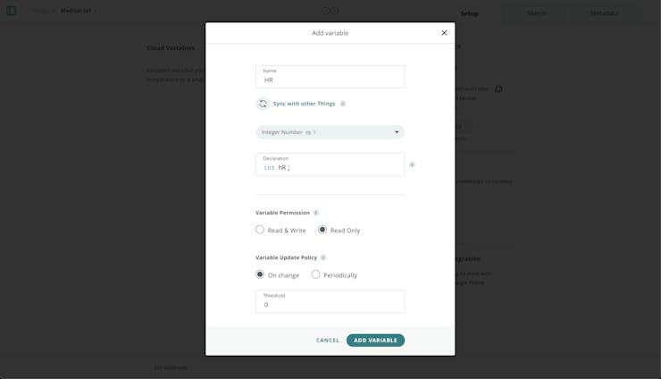
Similarly, create other variables also.
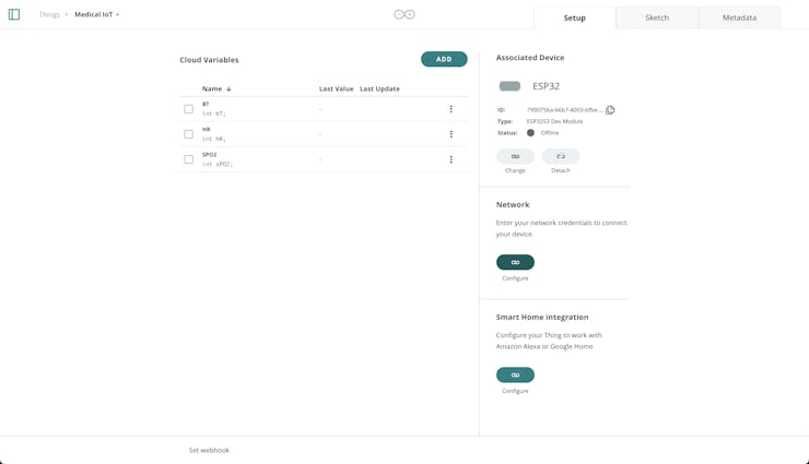
3. Finally configure your network in the Network section. Here you will enter your Wi-Fi® credentials, and your Secret Key, obtained when configuring your device.
All the above configurations have now been generated into a set of files that can be accessed in the Sketch tab.
3. Compile and Upload Sketch
Once our sketch is prepared, we can compile and upload it to the board. The duration of this process may vary based on the sketch's size. Do the following steps carefully to upload the code.
Ensure the Create Agent is installed to enable communication between Arduino Cloud and your board within the web interface.
Confirm that your board is connected and visible in the board selection menu.
Click the verify/upload button to compile and upload your sketch to the board.
Wait for the code to be successfully uploaded; the duration may vary depending on the size of your sketch.
Open the serial monitor tool to check for debug messages. Any connection errors will be printed here if encountered.
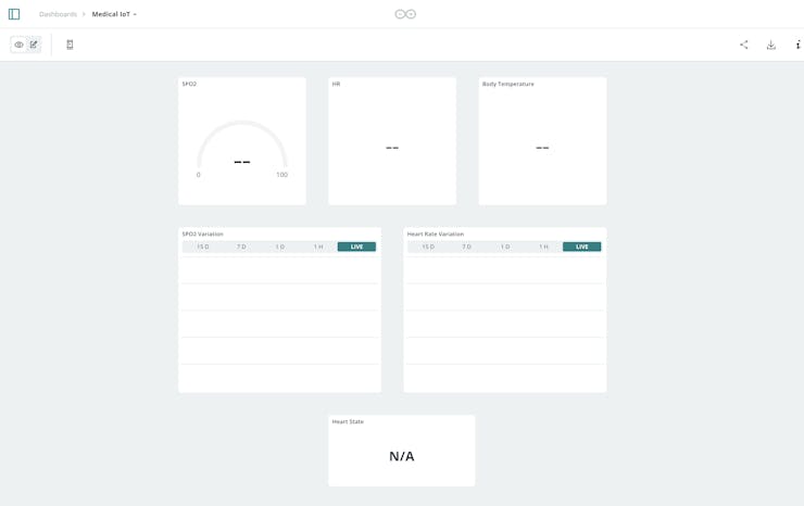
4. Create Dashboard
To create our dashboard follow these steps.
Go to Dashboards, and create a new dashboard.
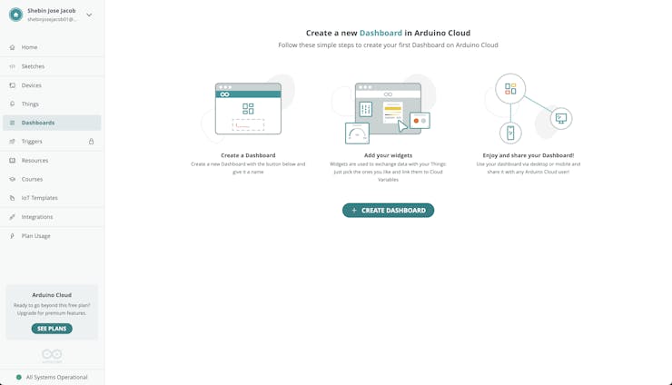
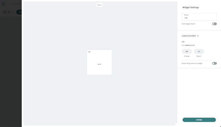
Click on the edit button at the top left, then on the "Add" button. Select the Thing you want to associate it with, and then click on "Create Widgets".
TinyML Model Training With Edge Impulse Integration
TinyML, or Tiny Machine Learning is a cutting-edge field in machine learning that focuses on deploying lightweight models directly onto edge devices, such as microcontrollers, sensors, and other embedded systems. These models are designed to perform inference tasks efficiently with minimal computational resources, making them ideal for applications requiring real-time processing, low latency, and low power consumption.
In the context of our project, incorporating a TinyML model for classifying heart sounds adds significant value:
Real-time Diagnosis: Deploying a TinyML model directly on our device enables real-time analysis of heart sounds without relying on external processing or internet connectivity. This allows for immediate feedback to the user and timely detection of potential abnormalities
Low Power Consumption: TinyML models are optimized for efficiency, allowing them to run inference tasks on battery-powered devices for extended periods. This is crucial for wearable and portable health monitoring devices, ensuring continuous operation without frequent recharging.
Improved Accessibility: Integrating intelligent analysis capabilities directly into a portable device enhances accessibility to healthcare services, particularly in remote or underserved areas where access to specialized medical facilities may be limited.
Training a TinyML model using Edge Impulse involves several steps, from data collection and preprocessing to model training and deployment. Let's start by creating the project on Edge Impulse Integration on Arduino Cloud.
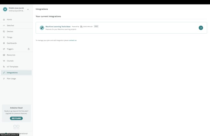
1. Navigate to Integrations on Arduino Cloud
2. Click on the Machine Learning Tool Base integration powered by Edge Impulse
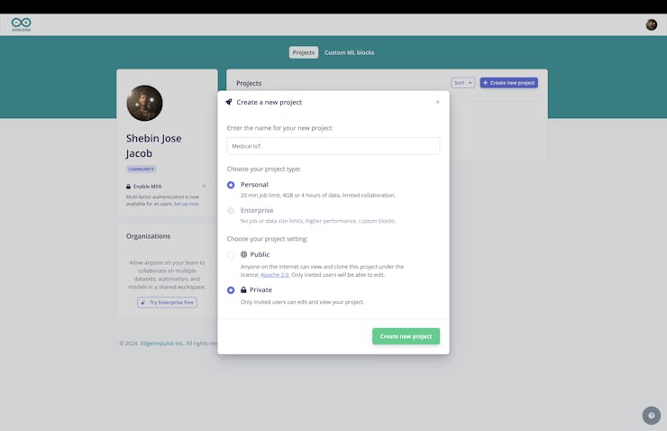
3. Create a New Project
Data Collection
Data collection forms the foundation of the TinyML model, providing the raw material for training and validation. In our case, we are using research-grade data publicly available on the internet.
This research paper proposes an improved, automatic classification algorithm for cardiac disorder by heart sound signal. They extract features from phonocardiogram signals and then process them using machine-learning techniques for classification. Also, they have provided a database of 5 categories of heart sound signals (PCG signals) from various sources which contain one normal and 4 are abnormal categories. The abnormal categories are Aortic Stenosis (AS), Mitral Regurgitation (MR), Mitral Stenosis (MS), and Mitral Valve Prolapse (MVP).
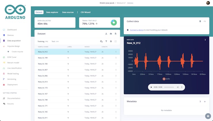
We are using this dataset for our TinyML model training. To upload the data navigate to the Data Acquisition tab.
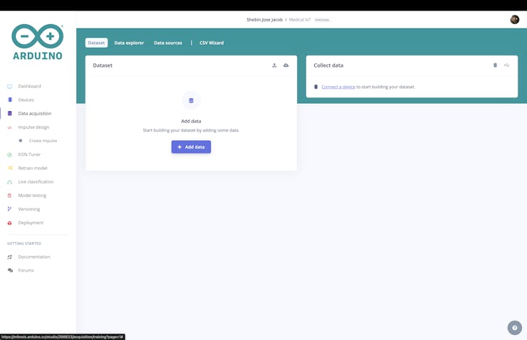
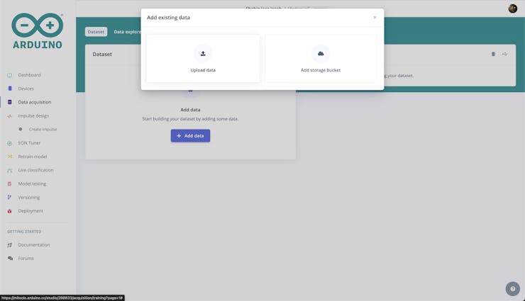
Click on Add Data and upload the dataset.
The dataset consists of 200 audio files for each class with each having a duration of 2-3 seconds.
After successfully uploading the dataset it would look like this. If the train-test ratio is not around 80:20, perform a train-test split from the dashboard.
Impulse Design
An impulse in Edge Impulse is a specialized machine-learning pipeline designed to extract useful information from raw data and use it to make predictions or classify new data.
The impulse creation process typically consists of three primary stages: signal processing, feature extraction, and learning.
During the signal processing stage, the raw data undergoes cleaning and organization to prepare it for analysis. This step often includes noise removal and data preprocessing to enhance its suitability for subsequent stages.
In the feature extraction stage, significant characteristics or patterns are identified and isolated from the processed data. These extracted features serve as the essential elements for the learning block to classify or predict new data effectively.
Finally, the learning block takes charge of categorizing or predicting new data based on the features derived in the previous stage. This phase may entail training a machine learning model using the extracted features or employing alternative classification or prediction algorithms.
This is what our Impulse looks like.
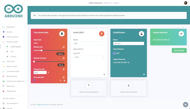
We've opted for Time Series Data as our input block. Given that each cardiac cycle spans about 0.8 seconds and our data durations range from 2 to 3 seconds, we've chosen a window size of 1000ms and a window increase of 100ms.
For our processing block, we've selected Audio MFCC. MFCC stands for Mel-frequency cepstral coefficients. It's a feature extraction technique widely used in audio signal processing and speech recognition. MFCCs are derived from the short-term power spectrum of a signal, mimicking the human auditory system's response to sound. The process involves several steps, including applying a mel-filterbank to the power spectrum, taking the logarithm of the filterbank outputs, and performing a discrete cosine transform (DCT) to decorrelate the coefficients.
Finally, for the learning block, we are using a Classifier block. This type of algorithm is designed to assign data to one of several predefined categories, and it is well-suited for the task of classifying heart sounds into one of five categories. By using classification as the learning block, we can categorize the heart sounds into one of five classes.
Data Processing
Navigate to the MFCC tab, where you'll find a number of parameters you can vary to alter the feature generation process.
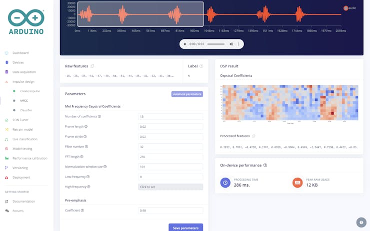
But we are keeping them to default and let's proceed to the feature generation process.
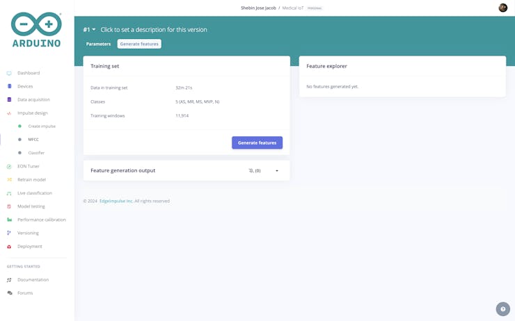
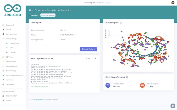
After the feature extraction process, we generated features for our dataset as shown here.
Model Training And Testing
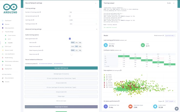
With the generated features ready, the next step is to proceed with training the model. Navigate to the Classifier Tab. Within this tab, you'll encounter three parameters and two architecture presets. These parameters and presets can be adjusted and experimented with until you achieve a satisfactory level of accuracy. Our training settings have yielded a model with an impressive training accuracy of 97.1%.
With our model now trained, it's time to evaluate its performance using previously unseen data. Head over to the Model Testing section and select Classify All. Below are the outcomes of the evaluation.
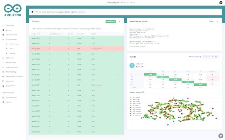
Our model has achieved a testing accuracy of 92.1%. With such strong performance, it's clear that our model is fully prepared for deployment.
Deployment
From the Deployment tab, build an Arduino Library. You can enable optimizations with EON Compiler if you like but is optional.
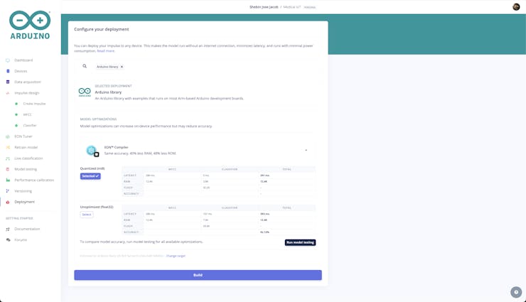
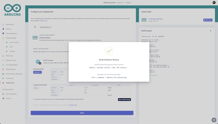
The build will output a zip file containing the model and some examples. Add the library to Arduino IDE using Sketch > Include Library > Add.ZIP library

Now upload the final code and PulseSync Pocket is ready for action.