
SLIDE is an open-source project that aims to educate and explore the world of holonomic robots. SLIDE can be implemented in various indoor environments like warehouses, restaurants, or hospitals where due to the proximity of people navigation of traditional robots is harder. Holonomic robots can easily navigate tight spaces as they can drive in any direction.
The aim of this project is not for commercial application but an educational one. Generally, students go after traditional drive robots like skid steering or Ackerman drive. This project aims to demonstrate the cool applications of holonomic drives and maybe increase some interest in this field.
INSPIRATION
.jpg)
The idea for SLIDE came to me during a boring office meeting. This is the actual sketch that I made and the only time I spent planning this project :) which had some unique consequences (we will explore them later) once I started playing with the robot.
Initially, SLIDE was supposed to have an arm on top to grab things and the Omni wheelbase robot to move objects from one place to another. I have used stepper motors in this project which are very precise. For a static predefined environment, SLIDE can move in a predefined path very accurately without needing expensive hardware like Lidar or depth camera. The software side is kept very simple to make it easier for beginners to explore.
I made this project months ago since then I have upgraded to aluminum extrusion instead of 3D printed parts.
This article is about the 3D printed version as 3D printing is more accessible and cheaper. This is the first part of the project I am still learning about the stepper motors and trying to improve the code. With some good code, we can make this robot accurate and precise at a fraction of the cost.
Before you start
Be patient :)
Before you start this project there is a lot to learn. Stepper motors are quite different than regular DC motors. I have included lots of external resources about stepper motors and stepper drivers please go through them before starting this project.
This article will mainly focus on the assembly of the robot and how to operate it. I did not want to complicate things so I kept the first part simple. In the next part, I will go into detail about the maths and kinematics of the Omni wheel. Let me know if there is any confusion on wiring or setting up the stepper drivers I will make a dedicated video explaining stepper motor operation in the context of this project.
Do not skip the external resources I have included in this article they will help you learn.
CAD MODEL AND 3D PRINTING
SLIDE has very few parts to 3D print but they take a lot of time to print :(
I used PLA to print which caused problems later on. Due to heat generated by the motors parts started to bend. I recommend printing in ABS or any other material that can handle temperatures up to 80C.
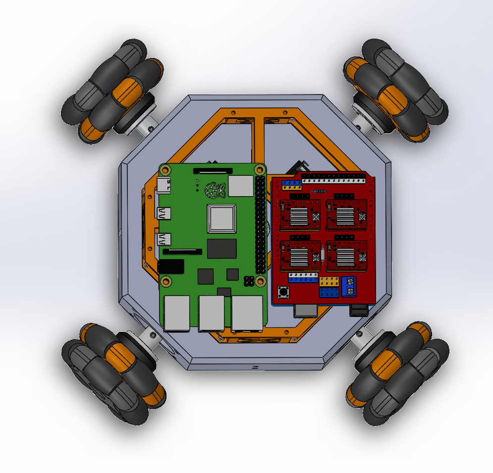
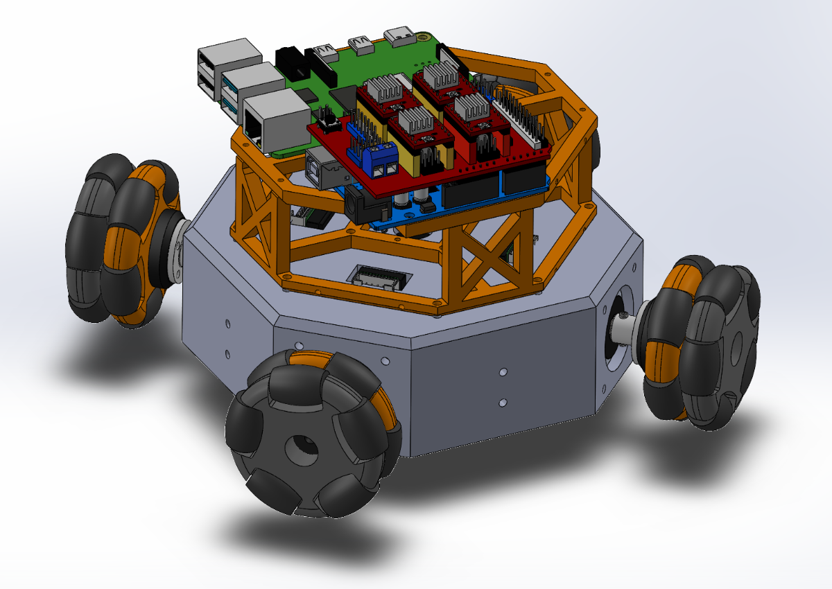
Solidworks model is also included in case you want to edit the model. You may download all the raw and STL files from GRABCAD
ASSEMBLY
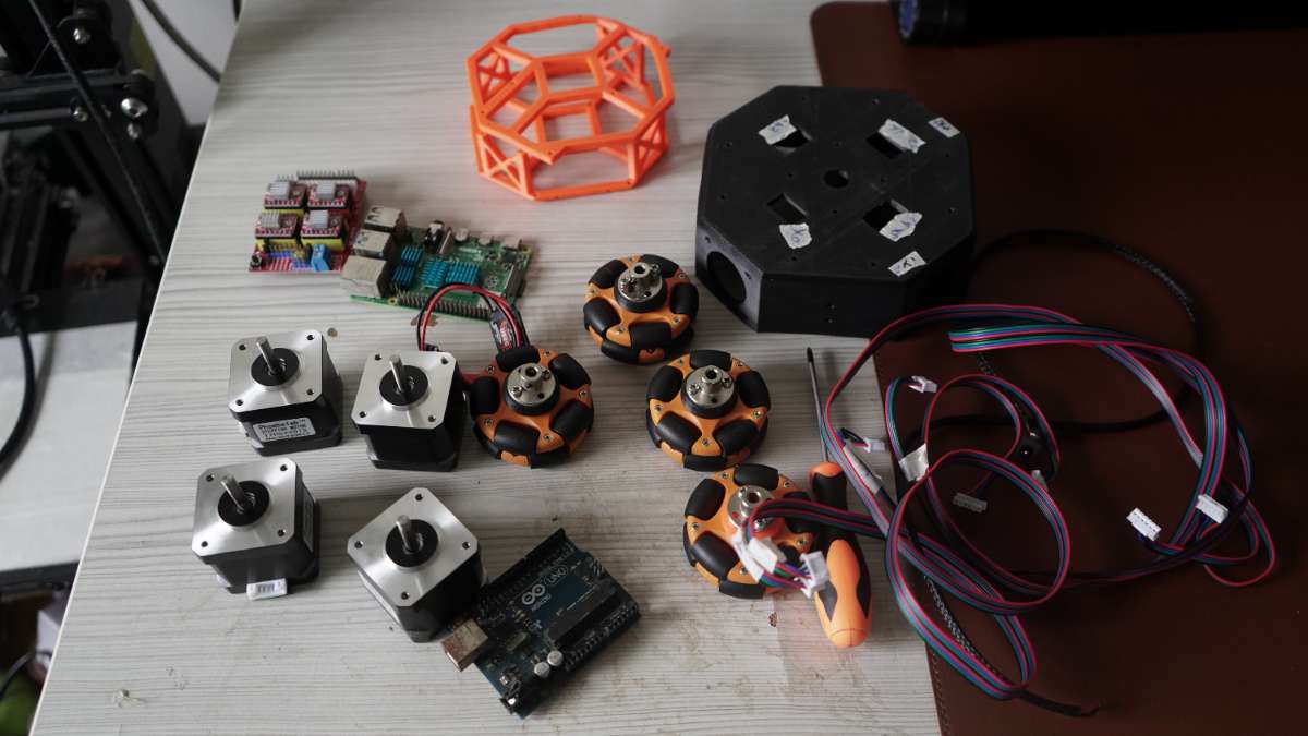
Fun part :)
Assembly is really easy to use 3MM screws to secure the motos and main chassis and 2MM screws for the orange wire cage.
BE CAREFUL THESE MOTORS ARE HEAVY DO NOT DROP THEM ON YOUR FEET. TAKE OFF YOUR HEADPHONES AND PAY ATTENTION WHILE HANDLING THEM I LEARNED THIS THE HARD WAY.
Nobody likes to be friends with a person with 9 toes luckily I am already married :)
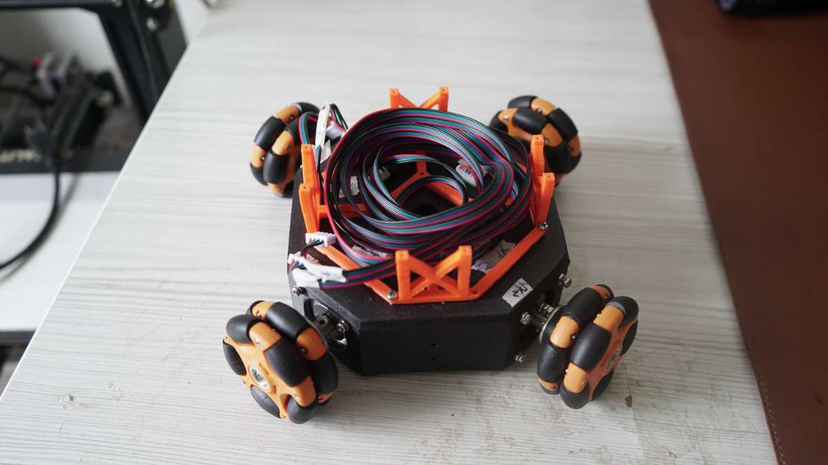
I bought the motors from a 3D printing store so they came with really long wires. They looked cute so I did not adjust the size instead I made that funny-looking cage just for holding the wires. It was meant to hold the batteries which I do not recommend as the motors generate a lot of heat and battery barbeque is not very healthy. I am using wall power for this project which we will explore later.
The really fun part is the couplings. I made coupling for coupling (1000+ IQ). These Omniwheels wheels are not made to be used with stepper motors so they do not have holes for screws I made a 3D printed attachment that has holes for screws and is mostly friction fit. This is the weakest part I recommend using 100% infill because it keeps on breaking.
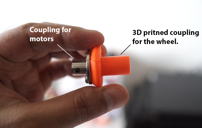
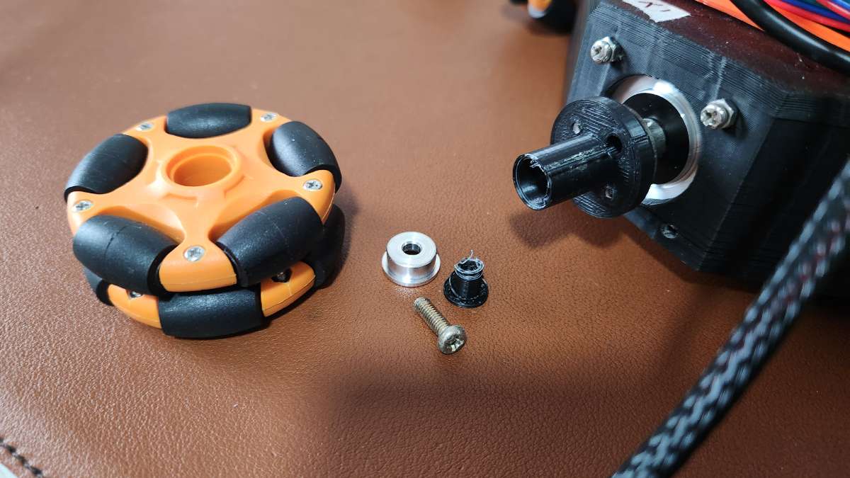
Don't be cheap, print a few spares and if possible use stronger material. If you want a more solid solution drill holes through the omniwheel and use long bolts to secure the metal coupling.
STEPPER MOTORS
Stepper motors for beginners are like really bad dancers of the motor world. They take one step forward, then two steps back, and just when you think they’ve got the rhythm, they will overheat and draw too much power if not calibrated properly burn your motor drives and house down.
Remember, though, that while stepper motors might be quirky, they’re also incredibly precise and versatile for all sorts of applications. Here are some people explaining stepper motors better than me. Watch these reference videos they will make your life easier later while debugging problems.
Stepper motor explained
Google "How to adjust Vref for stepper drivers"
Before powering anything you need to calibrate your stepper drivers(We are using A4988 stepper drivers). You cannot just plug the motors in. Depending upon your motor's current rating you will have to adjust the potentiometer of your driver.
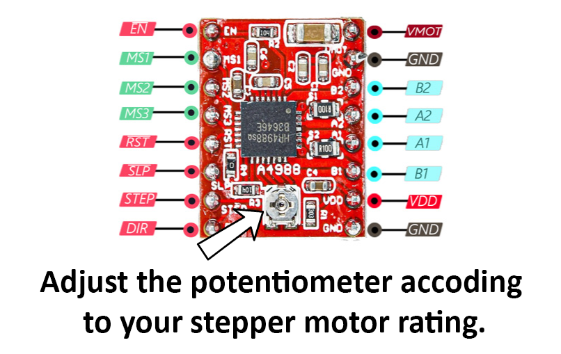
The process of doing this is different for different drivers. I have linked a few good articles on how to do this. Please read and watch all of them before powering up anything.
Please read these articles to understand the concept better.
- A4988 motor current tuning
- Vref Calculator: How to Tune Your Stepper Driver
- How To Correctly Set The Motor Current Limit On An A4988 Stepper Motor Driver
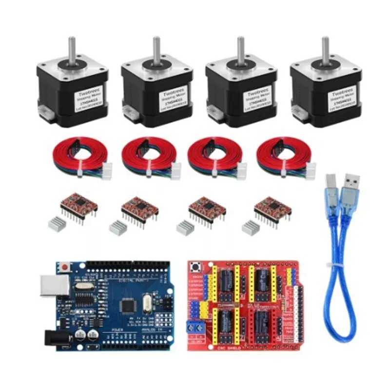
ARDUINO CNC SHIELD
The Arduino CNC Shield is a versatile and powerful expansion board designed to control CNC (Computer Numerical Control) machines such as 3D printers, laser cutters, and milling machines. By combining the CNC shield with an Arduino, you can control stepper motors with high precision and reliability.
Features of the Arduino CNC Shield
- Easy Integration: The shield seamlessly integrates with the Arduino, making it simple to set up and use.
- Stepper Motor Drivers: It supports up to four stepper motor drivers (A4988, DRV8825, or similar), allowing control of up to four stepper motors.
- Microstepping: The shield supports microstepping, which increases the precision of the motors. You can set it to various levels such as full step, half step, 1/4, 1/8, and 1/16 micro stepping.
- End Stops: The shield has inputs for end stops for all axes, ensuring the CNC machine operates within its physical limits.
- GRBL Compatibility: It is designed to work with GRBL firmware, a high-performance firmware for controlling CNC machines with Arduino.
In this project we are not using end stops we can add them later to detect if the robot bumps into anything. GRBL is another topic in short It makes our robot move like a 3D printer or laser cutter head. I made a custom program to read the G-code and move the robot because I was not able to set up GRBL with 4 motors but I have not included the code for it here :). It would be too much to explain in a tutorial but if you like more pain here is a video on expaling how to use GRBL with Arduino CNC shield.
How the Arduino CNC Shield Controls Stepper Motors
The CNC shield uses stepper motor drivers such as the A4988 to control the stepper motors. These drivers take care of the complex task of generating precise steps and microsteps. Here’s a simplified explanation of how it works:
- Direction and Step Signals: The Arduino sends direction and step signals to the stepper motor driver. The direction pin determines the rotation direction (clockwise or counterclockwise), while the step pin tells the driver to move the motor one step.
- Microstepping: Microstepping is a technique used to increase the resolution of the motor by dividing each full step into smaller steps. This allows smoother and more precise motor movements.
- Current Control: The driver also controls the current supplied to the motor coils, ensuring the motors operate efficiently without overheating.
We will use 1/16 micro stepping for our project so it is important to know how to set it another wire motor will vibrate a lot and make sad noises

Setting 1/16 micro stepping on the Arduino CNC Shield
To set the micro-stepping on the Arduino CNC Shield, you need to adjust the micro-step configuration pins (MS1, MS2, and MS3) on the stepper motor driver. For 1/16 micro-stepping, follow these steps:
Identify the Driver Pins: Locate the MS1, MS2, and MS3 pins on the stepper motor driver (e.g., A4988 ).
Set the Microstepping Configuration:
For A4988:
- MS1: High
- MS2: High
- MS3: High
Adjust the Jumpers: On the CNC shield, there are jumpers for each axis (X, Y, Z, and A). Place the jumpers as follows:
- Insert jumpers in the MS1, MS2, and MS3 positions for the respective axis to set them to high.
Example Configuration for 1/16 Microstepping
Insert the Jumpers:
- Place jumpers on MS1, MS2, and MS3 for each axis (X, Y, Z, and A) to set the pins to high.
Verify Connections:
- Ensure all jumpers are correctly placed, and the stepper motor drivers are properly seated on the shield.
I know you probably didn't understand a thing after reading this that's why I have included video links. People have been driving stepper motors using Arduino CNC shields since the Stone Age so do not worry there are tons of free tutorials and articles on the internet. Do not power the motors until you are confident.
Google "How to use stepper motors with Arduino CNC shield" You will get lots of tutorials with example code pick one of them understand it try to do the same if everything working proceed further with my code.
RASPBERRY PI
The virtual joystick program will run on Raspberry Pi 4. It comes with processing preinstalled you will need to install the Arduino if you want to program it using the Raspberry Pi otherwise you can program using your PC and just controlling the Robot you can use Raspberry Pi
We will connect to RPI using VNC its like sharing your desktop screen. Copy the virtual joystick program on RPI.
To connect to your Raspberry Pi 4 using VNC (Virtual Network Computing), follow these steps:
- Enable SSH and Configure Wi-Fi (if headless):
- If you’re setting up your Raspberry Pi without a monitor, enable SSH by creating an empty file named SSH in the boot partition of the SD card.
- Configure Wi-Fi by adding your network details to the wpa_supplicant.conf file in the boot partition.
2. Find the IP Address of Your Raspberry Pi:
- Boot up your Raspberry Pi and connect it to the same network as your PC.
- Use a network scanning tool or log in to your router’s web interface to find the IP address assigned to your Pi.
3. Install VNC Viewer on Your PC:
- Download and install VNC Viewer on your PC or Mac.
4. Connect to Your Raspberry Pi:
- Open VNC Viewer and enter the IP address of your Raspberry Pi (e.g., raspberrypi.local:1).
- Click “Continue” if you encounter a security warning.
5. Enter the VNC Password:
- When prompted, enter the VNC password (usually set during the VNC server setup on the Pi).
- Click “OK” to establish the remote desktop connection.
If Arduino is not connected to the RPi and you run the program it will give an error port not found so first find the correct com port of your Arduino enter it in the joystick program then run it.
To find the port to which your Arduino is connected to the Raspberry Pi, follow these steps:
- Open a terminal on your Raspberry Pi.
- Run the following command to list all available serial ports
dmesg | grep ttyLook for a name like ttyACM0 or ttyUSB0. This indicates the port where your Arduino is connected. Remember to disconnect the Arduino before running the command, and then connect it again to see the new port name if needed.
Once you enter the above command it will give you a list of attached USB devices to your PI. If only Arduino is connected to the USB terminal the following code in the joystick program will work if other devices are connected you may want to change the list number [0] to [1]. The list number depends on the number of USB devices connected. If the above commands show 3 devices connected then your list will range from 0 to 2 so experiment and change the number until the joystick connects with Arduino.
port = new Serial(this, Serial.list()[0], 115200);
CIRCUIT DIAGRAM
Sorry :) I am bad at drawing circuits.
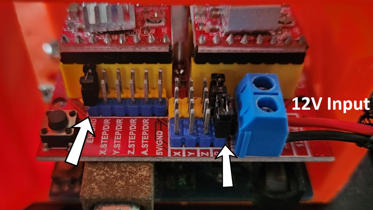
IMPORTANT: SET UP THE JUMPERS AS SHOWN BELOW. THERE SHOULD NOT BE ANY OTHER JUMPERS EXCEPT FOR THE MICROSTEPPING BELOW THE STEPPER DRIVERS.
This is the easiest electronics assembly you will do in your life. We are using shields so there is no soldering needed.
Arduino
- Mount the stepper drivers on the shield in the correct orientation.
- Mount the shield on the Arduino UNO.
- Before connecting the motors adjust the Vref for each motor driver.
- Then connect the motor wires to the shield.
Raspberry PI.
Use the official Raspberry PI instructions on how to set up PI if you are doing a fresh install after that. You will have to install the VNC server. Refer to the setting up Pi section.
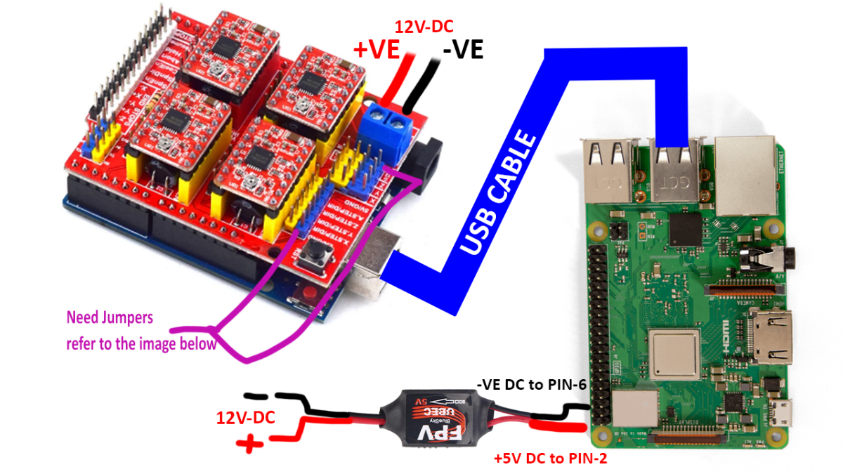
We will use a 12V DC power supply but RPI is not compatible with it so we will have to step down to 5V and supply the power using GPIO pins.
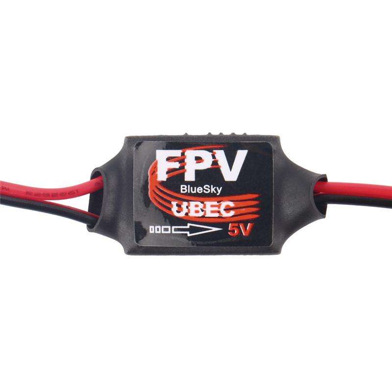
I am using a 12V to 5V UBEC it is used mostly in drones and is quite reliable. Be careful which is the output and which is the input side. The output of UBEC will go to RPI GPIO. For different RPI boards GPIO power pins might be different so please double check the pinout to find which is the power input GPIO you cannot just plug in any pin.
Read this article for more info
We will use pin 2 for + ve input and pin 6 for -Ve input.
If you are not confident you can just use a power bank to power the PI. Don't use GPIO power and power bank together.
.png)
Arduino will be connected to RPI via a USB cable and draw power from the RPI USB. The shield will be directly connected to the 12V power supply. Although the shield is sitting on top of Arduino it does not draw power from it as long as jumpers are set as shown below.
CODE

We will use Arduino IDE to program the Arduino to control the stepper motors and Processing to run the Joystick interface. The processing program will run on Raspberry PI. In the video I am using my phone to connect to RPI using the VNC server you can use your PC also and use the mouse to move the joystick.
Arduino code
We'll use the AccelStepper library to handle motor control and serial communication to receive joystick values. This guide will cover the necessary libraries, installation steps, and the logic behind the code.
Required Libraries
- AccelStepper: This library allows you to control stepper motors with ease. It supports various types of drivers and provides functions for speed control, acceleration, and more.
- MultiStepper: This library helps manage multiple stepper motors simultaneously.
Installing the Libraries
To install these libraries, follow these steps:
- Open the Arduino IDE.
- Go to Sketch > Include Library > Manage Libraries...
- In the Library Manager, search for "AccelStepper" and click on the "Install" button.
- Similarly, search for "MultiStepper" and install it.
Finding the Steps Per Revolution
The steps per revolution of a stepper motor depend on the motor's design and the micro-stepping setting of the driver. For example, a common stepper motor might have 200 steps per revolution (1.8 degrees per step). If you use a driver set to 1/16th micro-stepping, the effective steps per revolution will be:
Steps per revolution= Motor steps × Microstepping
For a 200-step motor with 1/16th micro stepping:
Steps per revolution = 200×16 = 3200
Code Breakdown
Libraries and Definitions: We include the necessary libraries and define constants for the number of steps per revolution, motor pins, and motor settings.
Creating Stepper Instances: We create AccelStepper instances for each motor, specifying the driver type and pin configuration.
Setup Function: The setup() function initializes serial communication and configures each stepper motor with maximum speed and acceleration.
Loop Function: The loop() function continuously checks for incoming serial data. When data is available, it reads and parses joystick values calculates motor speeds, and sets the speeds for each stepper motor. The motors are then moved at the specified speeds using
runSpeed()How It Works
- Serial Communication: The Arduino reads joystick values from the serial input. These values are expected to be in CSV format (e.g., "10,20,-30,40").
- Motor Control: Based on the joystick input, the code calculates the speed for each motor. The calculations are done by subtracting the right joystick values from the left joystick values to determine the direction and speed.
- Moving the Motors: The setSpeed() function sets the speed for each motor, and the runSpeed() function continuously moves the motors at the set speed.
These are the pins to which our motor driver is connected we do not have to worry about them as we are using CNC shield.
//Define the pins for each stepper motor
#define MOTOR1_STEP_PIN 2
#define MOTOR1_DIR_PIN 5
#define MOTOR2_STEP_PIN 3
#define MOTOR2_DIR_PIN 6
#define MOTOR3_STEP_PIN 4
#define MOTOR3_DIR_PIN 7
#define MOTOR4_STEP_PIN 12
#define MOTOR4_DIR_PIN 13
The simplest form of control is to move the robot. I have implemented X-Y control to move in one direction 2 motors move together. It is easy to understand and implement for beginners. There are more complicated configurations for Omni wheel robots like the X configuration where 4 motors are required to move in one direction this requires some vector calculation which we will cover in the future.
// Calculate motor speeds based on joystick values
int motorXSpeed = leftX - rightX;
int motorYSpeed = leftY - rightX;
int motorZSpeed = -leftX - rightX;
int motorASpeed = -leftY - rightX;
Notice I am not printing anything to serial and the code is simple. It is because any delay in the calculation of motor steps and timings makes motors vibrate and make noise. This is the reason I have kept this part very simple. Later version I will switch to ESP32 which is more powerful and has FREERTOS.
This part reads the values sent from the virtual joystick and separates them into values for each motor
  // Check if data is available on the serial port
  if (Serial.available() > 0) {
    // Read the CSV values
    String input = Serial.readStringUntil('\n');
    int values[4];
    int i = 0;
    char *ptr = strtok((char *)input.c_str(), ",");
    while (ptr != NULL) {
      values[i++] = atoi(ptr);
      ptr = strtok(NULL, ",");
    }
Virtual Joystick - Processing code
I am using Processing for making the virtual joystick. It's easy and simple to understand. I have used processing in many of my projects it is java Java-based programming language really good for quick prototyping and visualization.
Click here to download the processing
Explanation of the Code:
Importing Libraries:
import processing.serial.*; imports the serial library for serial communication.Global Variables:
- Serial port; initializes the serial port object.
- Variables like leftBoundaryX, leftBoundaryY, rightBoundaryX, rightBoundaryY, etc., are declared to store the positions and sizes of the joystick boundaries and sticks.
Setup Function:
size(600, 400); sets the window size to 600x400 pixels.
The positions of the joystick boundaries and sticks are initialized.
port = new Serial(this, Serial.list()[0], 115200); initializes the serial communication using the first available serial port at a baud rate of 115200.
Draw Function:
background(255); sets the background color to white.- The boundaries and sticks are drawn using ellipse and line functions.
- The joystick values are mapped from screen coordinates to a range of -2000 to 2000 using the map function.
- The values are concatenated into a CSV string and sent to the Arduino over the serial port using port.write(csvData);.
- The values being sent are printed to the console using println.
mouseDragged Function:
- Checks if the mouse is dragging the left or right stick within their respective boundaries.
- Updates the position of the stick being dragged.
mouseReleased Function:
- Resets the positions of both sticks to the center of their respective boundaries when the mouse is released.
This part gets the values of the X-Y joystick when they are moved.
void mouseDragged() {
  // Check if the mouse is dragging the left stick within its boundary
  if (dist(mouseX, mouseY, leftBoundaryX, leftBoundaryY) < boundarySize / 2 - stickRadius) {
    leftStickX = mouseX;
    leftStickY = mouseY;
  }

  // Check if the mouse is dragging the right stick within its boundary
  if (dist(mouseX, mouseY, rightBoundaryX, rightBoundaryY) < boundarySize / 2 - stickRadius) {
    rightStickX = mouseX;
    rightStickY = mouseY;
  }
}
Once the joystick is moved we get the values. These are packed in the CSV format and sent to Arduino which is connected using a USB to the Raspberry Pi
// Create CSV data string from joystick values
  String leftValues = leftXAxis + "," + leftYAxis;
  String rightValues = rightXAxis + "," + rightYAxis;
  String csvData = leftValues + "," + rightValues + "\n";

  // Send the values to the Arduino over the serial port
  port.write(csvData);
CONTROLLING SLIDE
It's easy :)
.png)
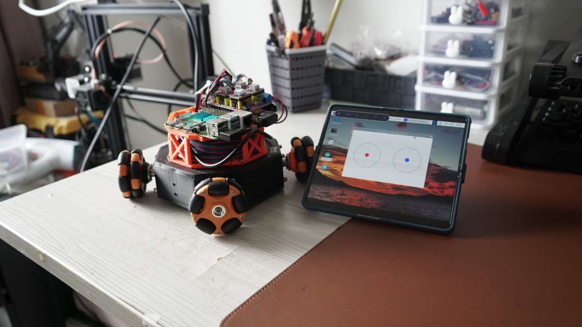
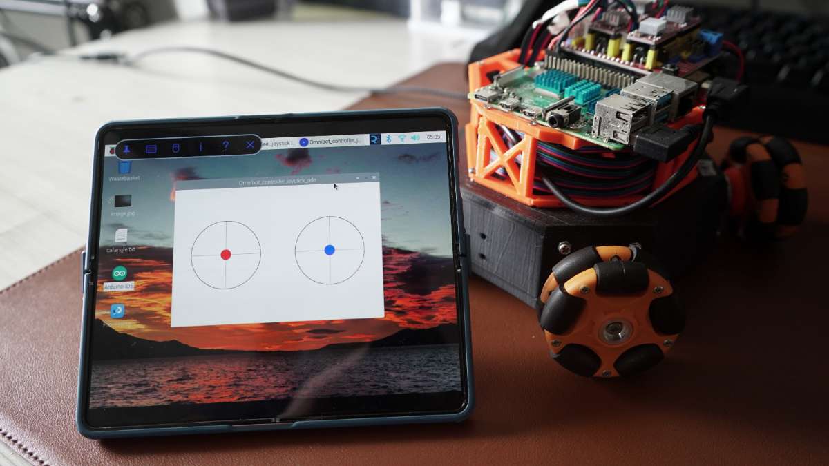
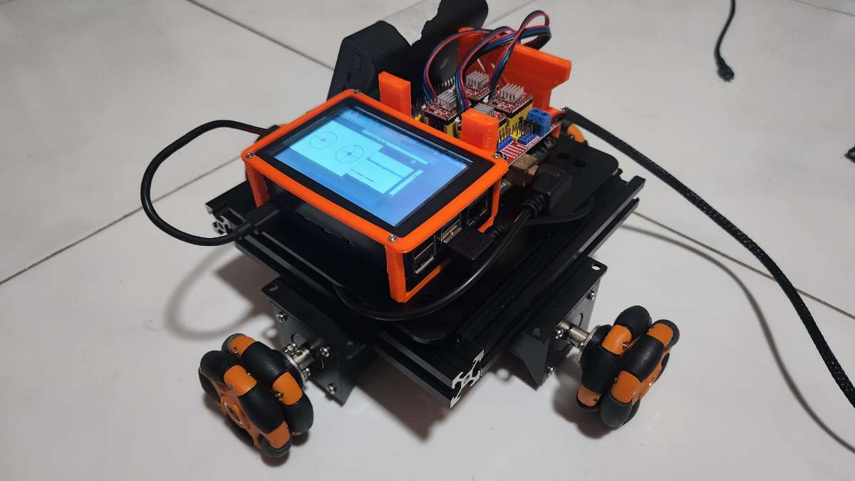
The virtual joystick program will help you move SLIDE. The left joystick is for forward, backward, left, and right movement and the right joystick controls the rotation. You can only move one stick at a time. SLIDE will adjust its speed depending on how far you move the joystick. I am using VNC on my phone so it gives the vibe of a handheld controller :) go make your friends jealous.
Right now RPI is underutilized it is only running the joystick interface. This is the first part so I have kept things simple. You can run third-party programs like GRBL on Pi and make SLIDE move like a CNC plotter. It will take time for me to update this project as I have a full-time job but there are already many tutorials available on the internet so please experiment with them.
PROBLEMS
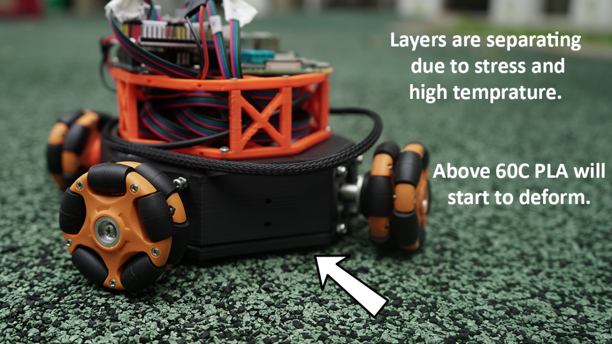
Heat and PLA are not a good combination. Layers are peeling off from 3D-printed parts. This can be easily solved by switching to materials that can handle high temperatures like ABS.
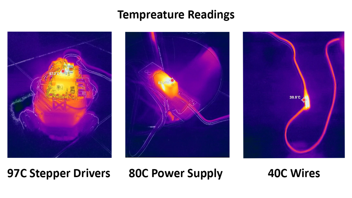
Stepper motors continuously draw the power even when they are not moving due to which temperature keeps on rising. You can see above that drivers are reaching up to 97C. Everything is packed together which increases the temperature further. I did not use proper gauge wires and a good quality power supply as this was an initial prototype. Stepper drivers have a feature to turn the motos off when not in use. I forgot to implement it in the code.
I have learned a lot from building this prototype and from my mistakes. I will implement my learning in the next version.
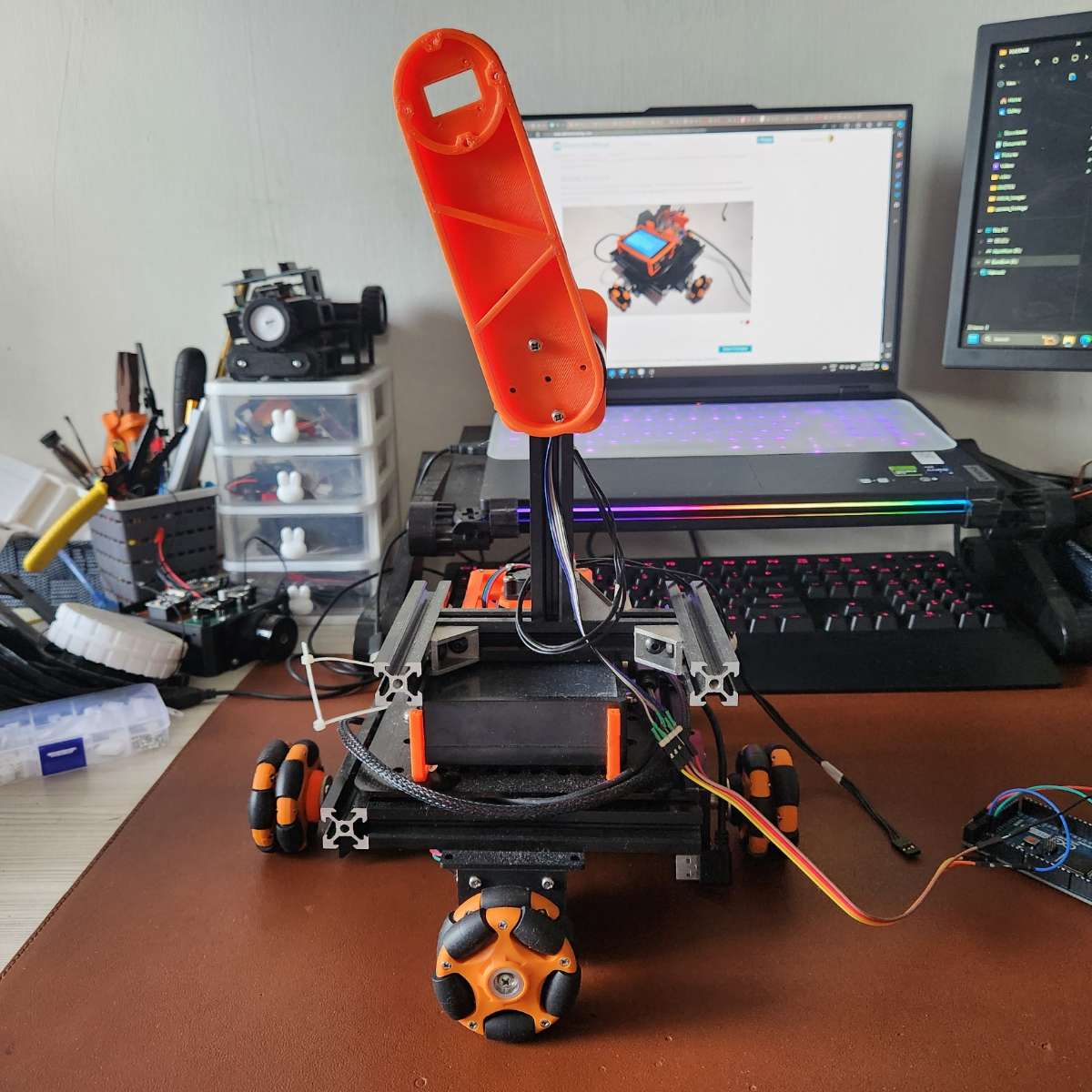
FUTURE UPGRADES
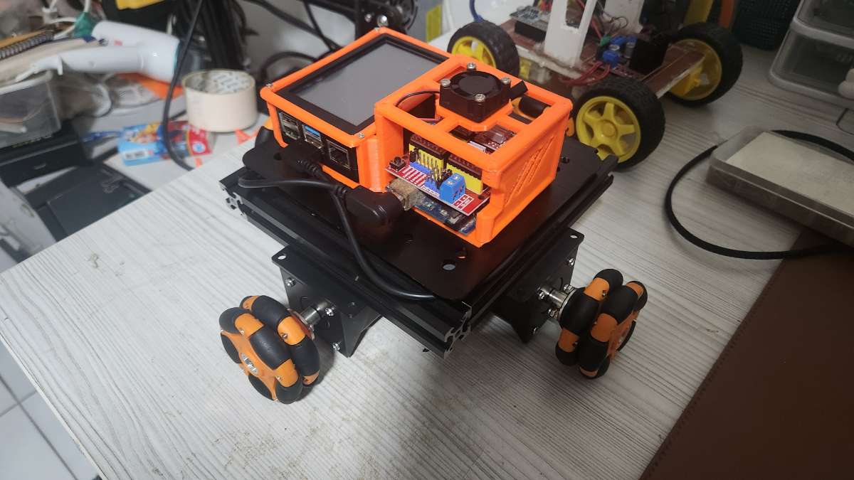
Better chassis that can handle the load of motors and heat. I have already made one using aluminum extrusions. I have attached a screen on RPI so there is no need for a VNC server. You can control SLIDE using a Python program on a PC or an Android app.
I am also working on the arm. It will use brushless motors so now I am learning FOC control. I made a baby balancing robot using these motors. You can see them on my Instagram
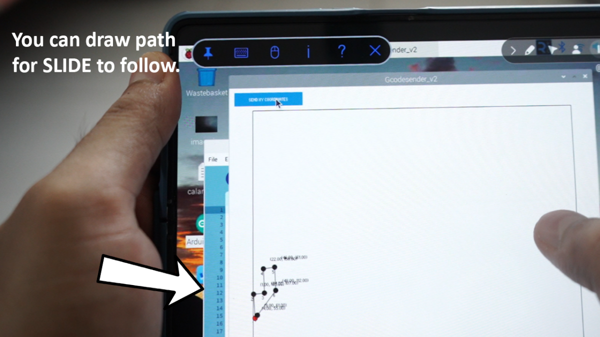
Did I forget to tell you SLIDE can follow pre-defined waypoints?
More on this in the next update.
Let me know if there are any further issues :)