Problem Statement:
- According to the report of NCRB (National Crime Record Bureau) 2019, A total of 4,05,861 cases of crime against women were registered during 2019, showing an increase of 7.3% over 2018 (3,78,236 cases).
- An increasingly large number of college-going women taking public transportation in Delhi have resorted to carrying pins, pen knives, and even daggers as a deterrent. Others have taken self-defense classes.
- A recent survey revealed that approximately 90 percent of college women in New Delhi have experienced sexual harassment in some shape or form. Yet, it is estimated that only about 1 in 10000 eve teasing occurrences are reported to the police.
- In India, eve-teasing affects every woman who dares to come out of her home, in some form or the other. Every woman has a private space. Any person entering her private space causes trouble to her or injures her. It is noticed in all places like Beaches, roads, cinema halls, buses, and educational institutions.
Project description:

Smart slipper consists of a High voltage Generator, ESP01 & Transistor, basically when this ESP01 receives data from Smart Pendant, A (Transistor)switch is provided on the shoe to start the voltage multiplier circuit which initiates a shock when touched by some person gives a shock to repel him/her and it can prevent the danger.
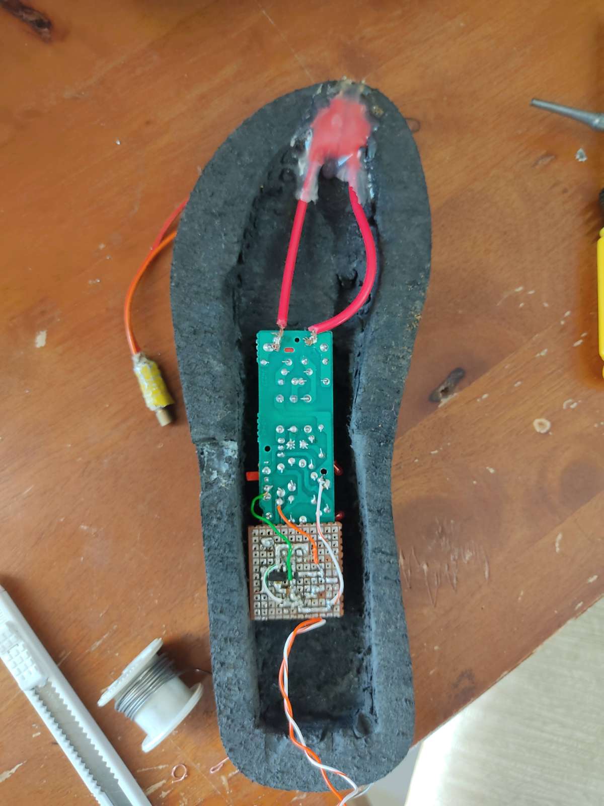
Smart Pendant
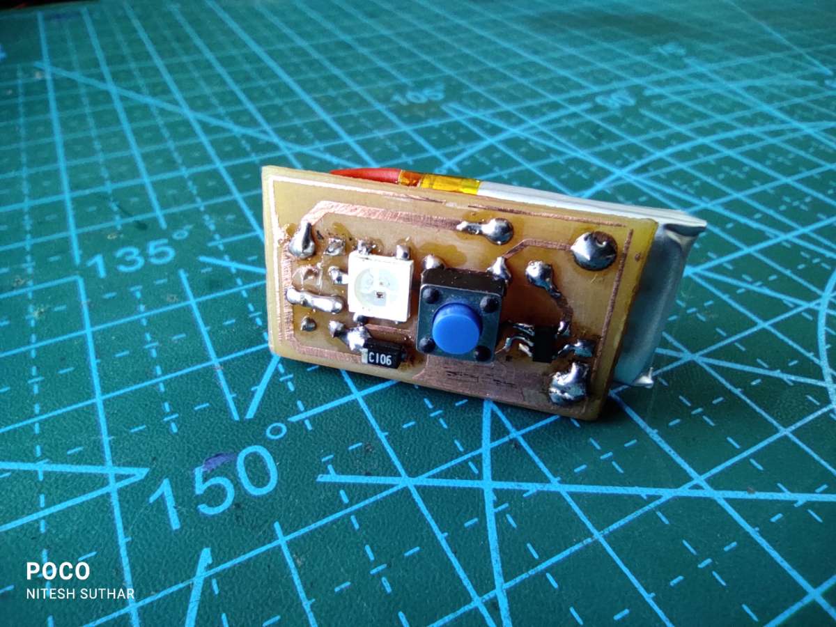
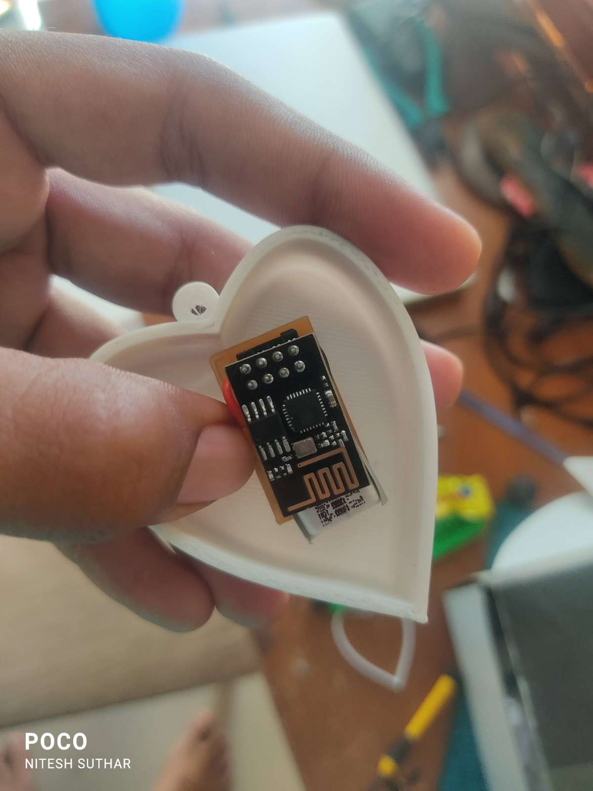
The smart pendant consists of ESP01, Push Button, Diode & Battery.
Link:- https://www.instagram.com/reel/CZMm05-Fi1_/
Working & Code Explanation:

ESP-NOW is a fast communication protocol that can be used to exchange small messages (up to 250 bytes) between ESP8266 boards. here we use one-way communication between two ESP8266-01. Smart pendant sends data to slipper ESP8266-01.
To communicate via ESP-NOW, you need to know the MAC Address of the ESP8266 receiver. Each ESP8266 has a unique MAC Address and that’s how we identify each board to send data to it using ESP-NOW...
#include <ESP8266WiFi.h>

void setup(){
  Serial.begin(115200);
  Serial.println();
  Serial.print("ESP8266 Board MAC Address:  ");
  Serial.println(WiFi.macAddress());
}

void loop(){

}
After uploading the code, open the Serial Monitor at a baud rate of 115200 and press the ESP8266 RESET button.

Here we need our smart slipper ESP8266-01's MAC address, So save that mac address, because we need it in our main Code.
ESP8266-01 NodeMCU Smart Pendant Sketch (ESP-NOW):
#include <ESP8266WiFi.h>
#include <espnow.h>

int help;
uint8_t broadcastAddress[] = {0xE8, 0xDB, 0x84, 0xA8, 0xC5, 0x63}; // Write Recevier Mac address

typedef struct struct_message {
int help;
} struct_message;

struct_message myData;

void OnDataSent(uint8_t *mac_addr, uint8_t sendStatus) {
  Serial.print("Last Packet Send Status: ");
  if (sendStatus == 0){
    Serial.println("Delivery success");
  }
  else{
    Serial.println("Delivery fail");
  }
}

void setup() {

  Serial.begin(115200);
  pinMode(2,INPUT);
  WiFi.mode(WIFI_STA);


  if (esp_now_init() != 0) {
    Serial.println("Error initializing ESP-NOW");
    return;
  }

  esp_now_set_self_role(ESP_NOW_ROLE_CONTROLLER);
  esp_now_register_send_cb(OnDataSent);


  esp_now_add_peer(broadcastAddress, ESP_NOW_ROLE_SLAVE, 1, NULL, 0);
}

void loop() {
    int help = digitalRead(2);
    if(help == 1){
    myData.help = 1;
    Serial.println("Send a new message 1");
    esp_now_send(broadcastAddress, (uint8_t *) &myData, sizeof(myData));

    }
    if(help == 0){
    myData.help = 0;
    Serial.println("Send a new message 2");
    esp_now_send(broadcastAddress, (uint8_t *) &myData, sizeof(myData));
    }
}
How the code works:
- First, include the ESP8266WiFi.h and espnow.h libraries.
#include <ESP8266WiFi.h>
#include <espnow.h>- In the next line, you should insert the ESP8266 receiver MAC address.
uint8_t broadcastAddress[] = {0xE8, 0xDB, 0x84, 0xA8, 0xC5, 0x63}; // Write Recevier Mac address
In our case, the receiver MAC address is: E8:DB:84:A8:C5:63, but you need to replace that variable with your own MAC address.
- Then, create a structure that contains the type of data we want to send. Here int the variable type we used. We called this structure struct_message
typedef struct struct_message {
int help;
} struct_message;- Next, define the OnDataSent() function. This is a callback function that will be executed when a message is sent. In this case, this message simply prints if the message was successfully sent or not.
void OnDataSent(uint8_t *mac_addr, uint8_t sendStatus) {
  Serial.print("Last Packet Send Status: ");
  if (sendStatus == 0){
    Serial.println("Delivery success");
  }
  else{
    Serial.println("Delivery fail");
  }
}- Set the device as a Wi-Fi station:
WiFi.mode(WIFI_STA);- Initialize ESP-NOW:
if (esp_now_init() != 0) {
  Serial.println("Error initializing ESP-NOW");
  return;
}- Set the ESP8266 role:
esp_now_set_self_role(ESP_NOW_ROLE_CONTROLLER);It accepts the following roles: ESP_NOW_ROLE_CONTROLLER, ESP_NOW_ROLE_SLAVE, ESP_NOW_ROLE_COMBO, ESP_NOW_ROLE_MAX.
- After successfully initializing ESP-NOW, register the callback function that will be called when a message is sent. In this case, we register for the OnDataSent() function created previously.
esp_now_register_send_cb(OnDataSent);- Then, pair with another ESP-NOW device to send data:
esp_now_add_peer(broadcastAddress, ESP_NOW_ROLE_SLAVE, 1, NULL, 0);The esp_now_add_peer accepts the following arguments, in this order: mac address, role, wi-fi channel, key, and key length.
In the loop(), we’ll send a message via ESP-NOW every 2 seconds (you can change this delay time on the timerDelay variable).
- Here Button is connected with GPIO 02. we read button status according to changes int help.
pinMode(2,INPUT);int help = digitalRead(2);- myData is a structure. Here we assign the values we want to send inside the structure.
myData.help = 1;
myData.help = 0;- Finally, send the message as follows:
esp_now_send(broadcastAddress, (uint8_t *) &myData, sizeof(myData));we used if condition if button pressed, it sends 1 data to our Smart slipper. same as for button not pressed, it sends 0 data to Smart slipper.
if(help == 1){
    myData.help = 1;
    Serial.println("Send a new message 1");
    esp_now_send(broadcastAddress, (uint8_t *) &myData, sizeof(myData));

    }
    if(help == 0){
    myData.help = 0;
    Serial.println("Send a new message 2");
    esp_now_send(broadcastAddress, (uint8_t *) &myData, sizeof(myData));
    }
Circuit diagram of Smart pendant:
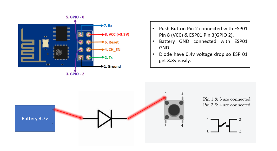
- Button connected with GPIO 2.
- Diode use for voltage drop because battery voltage 3.7v. ESP8266-01 operational voltage is 3-3.3v.
- when the button is pressed the GPIO 2 pin becomes HIGH. sends data to Smart slippers.
- For better battery life, also connect GPIO 2 with the VCC of ESP8266-01.So we button pressed at only that time ESP8266-01 becomes ON & with GPIO 2 pin also becomes with HIGH.
- The battery GND pin is connected with the GND of ESP8266-01.
ESP8266-01 NodeMCU Smart Slippers Sketch (ESP-NOW):
#include <ESP8266WiFi.h>
#include <espnow.h>


typedef struct struct_message {

    int help;

} struct_message;

struct_message myData;

void OnDataRecv(uint8_t * mac, uint8_t *incomingData, uint8_t len) {
  memcpy(&myData, incomingData, sizeof(myData));
  Serial.print("Int: ");
  Serial.println(myData.help);
  Serial.println();
  if(myData.help==1){
    digitalWrite(2,HIGH);
    Serial.println("ON");
    }
    if(myData.help==0){
    digitalWrite(2,LOW);
    Serial.println("OFF");
  }
}

void setup() {
  Serial.begin(115200);
  WiFi.mode(WIFI_STA);
  pinMode(2,OUTPUT);
  digitalWrite(2,LOW);
  if (esp_now_init() != 0) {
    Serial.println("Error initializing ESP-NOW");
    return;
  }

  esp_now_set_self_role(ESP_NOW_ROLE_SLAVE);
  esp_now_register_recv_cb(OnDataRecv);
}

void loop() {
 if(myData.help==0){
    digitalWrite(2,LOW);
    Serial.println("OFF");
    }
}- Similarly to the Smart pendant, start by including the libraries:
#include <esp_now.h>
#include <WiFi.h>- Create a structure to receive the data. This structure should be the same defined in the sender sketch
typedef struct struct_message {

    int help;

} struct_message;- Create a struct_message variable called myData.
Create a struct_message variable called myData.- Create a callback function that will be called when the ESP8266 receives the data via ESP-NOW. The function is called onDataRecv() and should accept several parameters as follows:
void OnDataRecv(uint8_t * mac, uint8_t *incomingData, uint8_t len){- We copy the content of the incomingData data variable into the myData variable
memcpy(&myData, incomingData, sizeof(myData));- Now, the myData structure contains several variables inside with the values sent by the sender ESP8266. To access variable a, for example, we just need to call myData.help
Serial.print("Int: ");
Serial.println(myData.help);- Register for a callback function that will be called when data is received. In this case, we register for the OnDataRecv() function that was created previously.
esp_now_register_recv_cb(OnDataRecv);- here we declared GPIO 2 pin for OUTPUT.
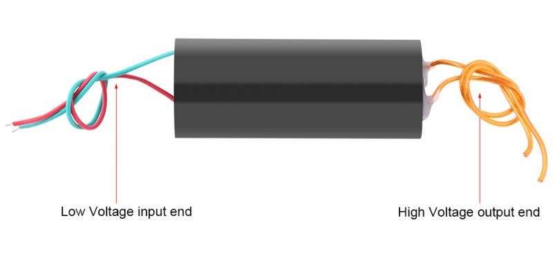
pinMode(2,OUTPUT);this GPIO 2 pin is connected with the Base of the transistor, the transistor act as a switch. & is connected with the High voltage generator.
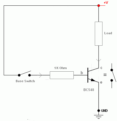
- The transistor working is shown in two pictures,
Case(i):- let's assume that The Output of GPIO2 is LOW. & in connection where Load mentioned at two terminals actually connected with input terminals of the High Voltage Generator. In this case, we are not getting any output from the High Voltage Generator.
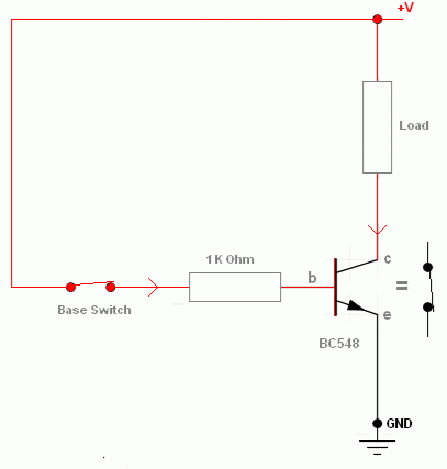
Case(ii):- The Output of the GPIO 2 pin is HIGH. At that time transistors acted as an ON switch. In this case, we get High voltage at the output terminals of the High Voltage Generator.
if(myData.help==1){
    digitalWrite(2,HIGH);
    Serial.println("ON");
    }
    if(myData.help==0){
    digitalWrite(2,LOW);
    Serial.println("OFF");
  }
i
Circuit diagram of Smart Slipper:
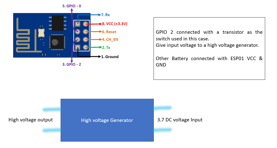
- GPIO 2 pin connected with Base of transistor as shown case(i)&(ii) diagram.
- A high voltage Generator is connected with a Collector & emitter of the transistor where you can show the load mentioned in the diagram of the case(i)&(ii).
- battery positive terminals & negative terminal is connected as shown in diagram of the case(i)&(ii). and VCC & GND of the ESP8266-01.you can also use a 3.3v Voltage regulator or Diode for the input voltage of ESP8266-01.
Video & Shorts link:
Shorts:- https://youtube.com/shorts/J-U90Oh6YJc?feature=share
Reels:- https://www.instagram.com/reel/Ceqt_NvFH_8/?utm_source=ig_web_copy_link