Clap automation-Clap to ON_OFF the Lights

Published Jun 26, 2022
 1 hours to build
 Beginner

I made this clap automation project. The works of the project is- when someone claps 2 times then the light (relay) turned on. Again someone claps 2 times then the light (relay) turned off. Through the project anyone can operate the lights via his/her claps.

display image

Components Used

BC547 TRANSISTORS
BC547 TRANSISTORS
1
GPCB
PCBs & Breadboards PadBoard-3U 2 sided with plated holes
1
ATMEGA328PB-AN
8-bit Microcontrollers - MCU ATMEGA328PB 20MHZ Extd. Temp
1
Diode 1N400x
Diode 1N400x
1
Screw and Stand-off Set
Adafruit Accessories Black Nylon Screw + Stand-off Set
1
Sound Sensor Module
Multiple Function Sensor Development Tools Sound Sensor Module
1
16MHz Crystal
Crystals 16MHz 20pF -20C 70C
1
Wire
Hook-up Wire 788133 RED 100 FT
1
Resistor 220 Ohms
Metal Film Resistors - Through Hole 220 OHM 1/4W 1%
1
Resistor 10 kOhms
Metal Film Resistors - Through Hole 10 kOhms 250 mW 1% 100 PPM / C
1
Capacitor 100 µF
Aluminium Electrolytic Capacitors - Radial Leaded 100V 100uF 105C 2k Hour Radial
1
Capacitor 22 pF
Multilayer Ceramic Capacitors MLCC - Leaded
2
Relay Module Single Channel
1
5VDC Adapters Power Supply
Wall Mount AC Adapters ac-dc, 5 Vdc, 2 A, SW, wall-plug, EU, P5 center pos, level VI, black
1
Lamps
Lamps Candelabra Screw 230V
1
Description

Circuit Connection


Hardware

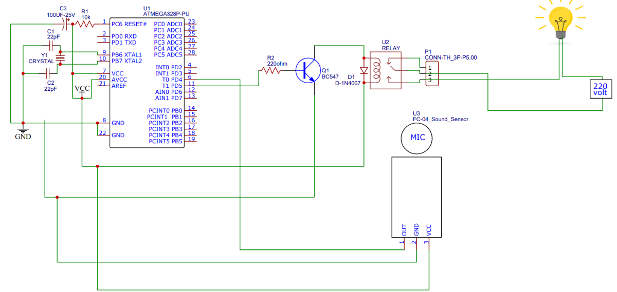
At first, I mount all the components in the zero pcb.  then I soldered all the components into the zero pcb using my schematic. you can download the schematic.


And I connect all the wires between the relay and the appliance(bulb). The connection between the relay and the bulb is -

          Input red wire to relay common point

          Bulb's red wire to relay NO point

          Input black wire to bulb's black wire

After soldering all the components into the zero PCB, I attached my circuit to the enclosure. 


Video

Codes

Downloads

Schematic_New Project_2022-06-26 Download
Comments
Ad