The BLDC motor controller for sliding gate.
It is a project that I have created based on the need to be able to open and close a sliding gate from 3 possible ways, taking into consideretion that there are already operating motors for sliding gates, but not that they meet the characteristics that this project does, Being a control board for DC motors, this has a lower consumption of power than the AC motor operators that currently exist, the fact of being DC allows me to control the opening and closing speed of the doors, something that I cannot do with the AC motor , in addition to having opening, closing and stop via RF control (433Mghz), I have added the same features, but from an app via Wi-Fi, and from a 3 buttoms that can be installed inside a house, apartment, or place where communication is required. This proyect also has hardware configurations which I will describe in detail below.
Lest get started describing the schematic:

Starting at the bottom right we have a transformer that will be responsible for providing power to the circuit and the motor, this transformer will have a ratio of 1:5, since we will reduce the domestic voltage 120v to 24 volts, this transformer is 500W, I have chosen a 500W transformer since we could have current peaks of up to 12Amperes. This transformer is followed by a bridge rectifier to convert the 24 volts ac into dc. The bridge rectifier has been chosen at 35 amps so when the motor is working at maximum torque the bridge rectifier is working at 40% of its maximum current capacity, then we have a filter capacitor of 18000 microfarads.
Transformer Features:
• 500 Watts of power.
• Due to the design of the motor casing, it is required to be a toroid.
• Ferrite as core material due to its low loss characteristics, little space and weight required.
• Voltage input 120Vac output 24Vac.
• Minimum current of 18 Amps.
Power Supply (LMR36510):
.png)
After the transformer and the rectified part we have the main power supply (LMR36510) that will reduce the input 24Vdc to about 15 Volts dc in order to power the parts of the circuit that require this voltage, such as the photocells, relay, magnetic lock , external buttoms, and the lamp, taking into account the consumption of each of the components connected to the power supply, I decided to choose this one that provides me with up to 1 amp maximum output, in its datasheet the manufacturer shows the topology above as indicated To use this integrated buck converter, the manufacturer also provides us with a table with the values of the components to be used for three different voltages, and in case of using another output voltage, it provides us with the formulas to calculate the resistance, capacitor and coil. also we have a 7805 (5V) voltage regulator conected after the power supplay, wich provide power the processor.
Regulator 3.3v (NCP1117LP):
.png)
After the voltage regulator (5v), i have another voltage regulator connected wich give 3.3V in the output, this voltage regulator provide power to the esp8266.
Module wifi (ESP8266):
.png)
The wifi module will be in charge of sending the data requested by the app to the microcontroller and vice versa, this wifi module is an esp8266 or also known as esp 01, which will be working in AP (Access point) mode, creating a wifi network (2.4Ghz ) with a password, this network will be pointing to a static IP address and a port to be able to make a socket to connect with the app. This module works at 3.3v with a consumption of less than 50 milliamps, it has a port (4 headers) to be able to reprogram it without having to remove it from the circuit, it also has two headers to put the esp8266 in boot mode, the boot mode consists of putting the GPIO0 pin to ground via a momentary jumper so that the micro can be programmed. I have chosen this module, since all electronic devices today are trending towards IOT (Internet of Things) technology, susers feel more comfortable having control or being able to monitor what is happening on their cell phone.
Module RF (CY11):
.png)
The RF module will allow me to receive the signals sent by the control at a frequency of 433 Megahertz and decode them through the microprocessor. This module is very practical to use, it has 5 pins, 3 being powered (2 GND, and one VCC) , an input for an antenna and to be able to amplify the reception that is 400 theoretical meters according to its manufacturer, and the last pin that is the one that sends the data.
Indoor Buttoms:
.png)
In this part of the circuit you can see 3 buttons that will allow us to control the sliding gate (Open, close and stop the door) from inside a house or desired place with a maximum distance of 20 wired meters, I have decided to use optocouplers to isolate the input circuit and the processor through light, the buttons will handle a voltage of 15v and on the other side of the optocouplers I will have 5v which are the ones that will be connected directly to the microprocessor, in the emitting part I have used 10Konhms resistors and the receiver side 1k onhms pull down resistors. It should be noted that I have used buttons for the schematic, but in reality it is a terminal which to go there, and the buttons connected to the terminal via cables.
Programm buttom:
.png)
Here and added a button which will allow me to program the controls that I want to control the door, this button will be left pressed for a while and the microprocessor will go into standby mode, once the button key is pressed, the buzzer beeps indicating that it has taken the signal and saved it. This button will also allow me to clear previously saved controls by pressing it for a longer time.
Limit Switch (career endings):
.png)
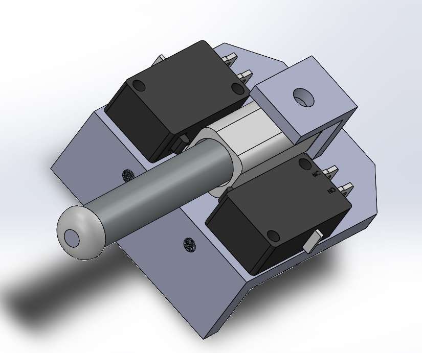
A fundamental part of the circuit are the limit switches that will indicate the position of the door (limit switches), completely open or completely closed and for this I need to use two switches, also connected to pull up through 1kohm resistors and when closing one of them get a logical 0, in the circuit they are directly connected to the processor.
Sensor current (ACS712):
.png)
The sensor to use is from a module that comes for Arduino, this works by hall effect where we put all the current of the circuit through it, and this will give me a voltage proportional to the current that crosses its pins. As you can see in the circuit I will not use the module, if not, I will take the integrated one and use the same module configuration, but directly on my pcb, this module is very simple to use and has a maximum current limit of 30 amps, the topology seen above is the one offered by the manufacturer.
Driver Bootstrap (L6388E):
.png)
In the control part of the brushless motor I have chosen a bootstrap driver that adapts to the needs of the circuit, which are to drive the motor windings which are in a Y configuration, these will be driven at high frequency and with a voltage of 24v , with this circuit and the processor I will be able to control the motor, in speed, turns, and braking.
Brushless Motor:
.png)
In the image you can see the connection of the BLDC motor where we have 3 coils connected in Y, and an encoder that works by hall effect that gives me the position of the motor through 3 cables in the following format (000, 001, 010, 011, 100, 101, 110, 111), the encoder is powered by 5 volts. I have chosen this motor because it is the one I have been able to get locally along with a casing, this motor is 24V with a maximum power of 220W, which is a relatively low power compared to other motors, this motor handles up to about 12Amps of current .
Did Switch:
.png)
The did switches will allow me to make certain configurations without needing the app, in case the user is archaic or simply does not want to use the app, these did switches will allow me to configure the auto-closing time with the first 3 (10s, 20s, 30s ), I can even add those times by activating more than one of them, the 4th is the lamp, if it is “on” the relay will start to activate and deactivate to do the blinking when the door is opening or closing, this is for the lamps that do not have the blinking effect, in case it is “off” the relay will keep providing the fixed 15 volts and thus connect a lamp that flashes (blinks alone), the 5th is the pedestrian in case it is on “on” the user will be able to open the door up to a certain point with button B of the control, if it is “off” this function is deactivated, the same for the 6th switch is the one for the output for the side lock, if it is in “on” I will be able to activate that output of the control button c and if it is "off" I will not be able to do it, the 7th switch called OFF, it is a switch that disables all the previous functions in case the user decides to do it from the app.
Output Relays:
.png)
These two relay outputs that we can see will go to a terminal block so that the user can connect, in the first a visual indicator lamp, it will turn on (flashing) when the door is opening or closing, and in the second the user can connect a lock magnetic that you can control from the 3rd button of your control.
Processor:
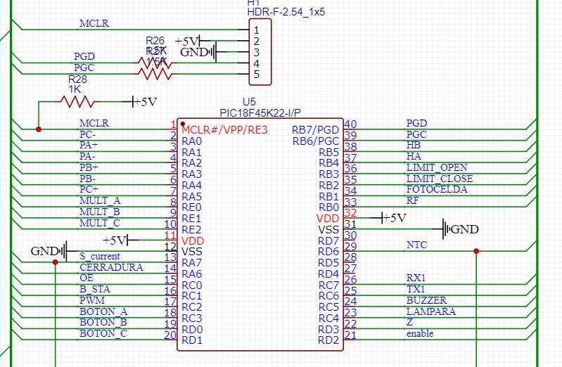
This is the processor wich is able to control all the operations, as you can see in the picture it is a PIC18F45K22, it has all the caracteristic (Interruptions, PWM, Timers, etc.) needed to make this proyect come true.
Pictures of the prototipe:
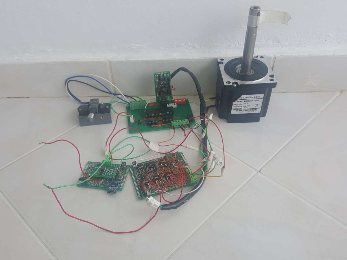
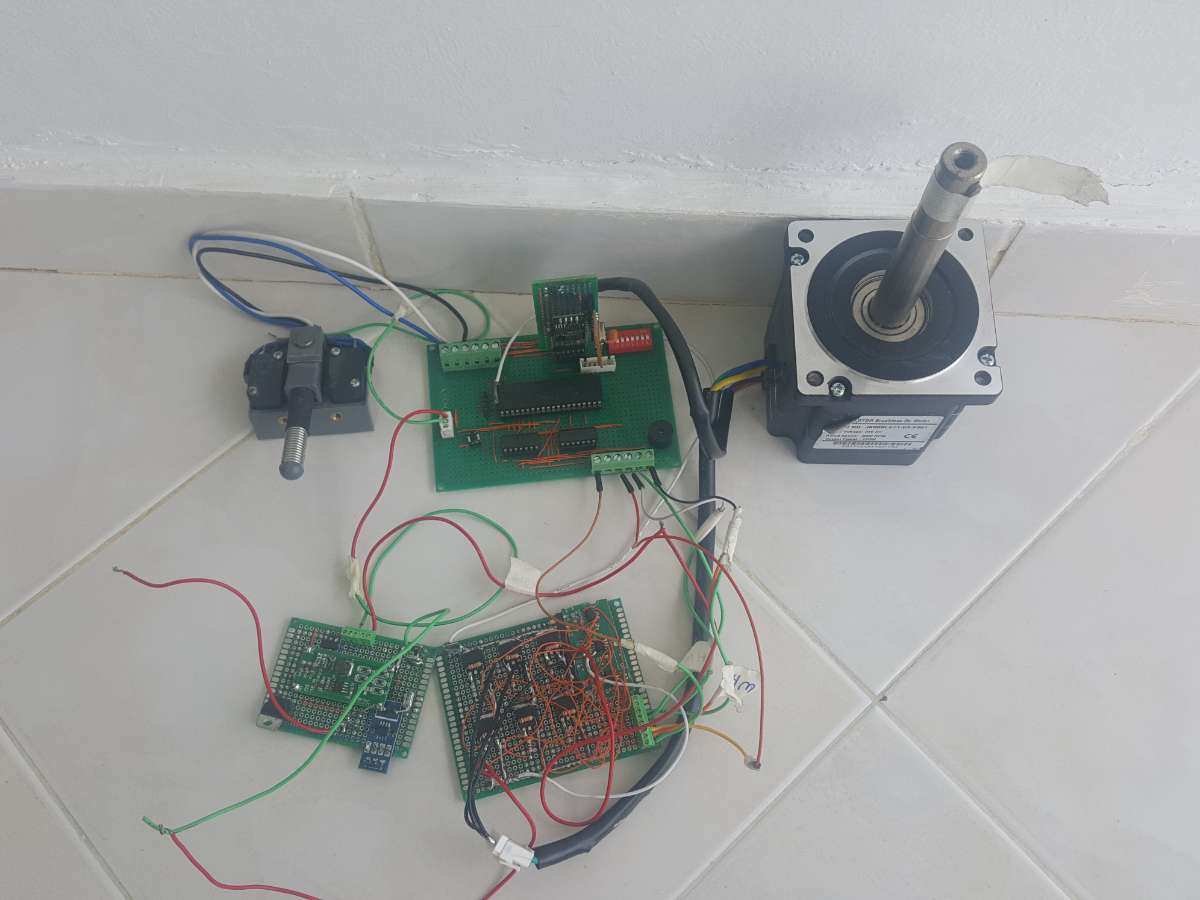
Signals of the coil:
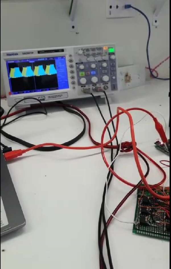
Video the motor working:
https://youtube.com/shorts/RnDztO68yB0
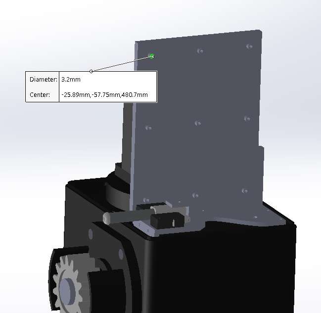
Limit Switch made it in solidworks:
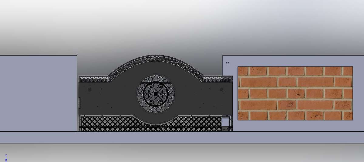
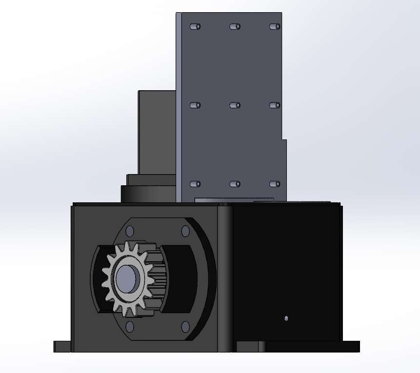
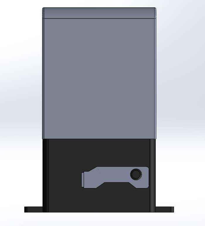
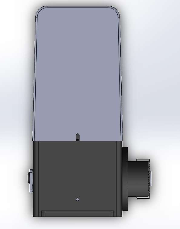
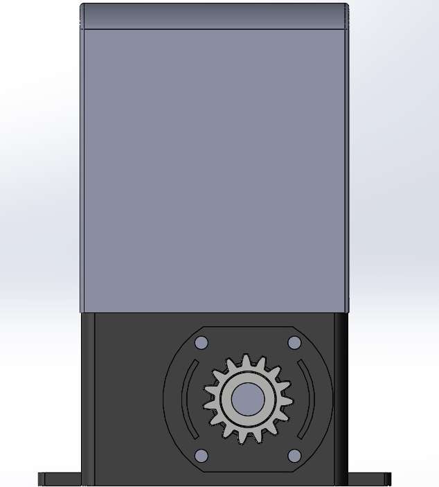
Some pictures of the 3D model (SolidWorks):
Note: I don't have a video with the complete operation of the project because when I was doing tests I burned the drivers and the pcb that I had made is still in China.