Introduction
I was on the lookout for a Smart Switchboard to control a few lights and Fans of my room. But all of them were expensive. It striked to me that I can also make a similar board myself. So here I am demonstrating the process of making one such smart relay board yourself.
Parts Breakdown:
- Part 1: Setting up the Electronics and Circuits
- Part 2: Setting up NodeMCU and Program
- Part 3: Creating a Flutter App for Added Ease
Part 1: Setting up the Electronics and Circuits
The circuit setup is pretty easy. We will use D2, D5, D6 and D7 pin of our NodeMCU board.
The Schematic below shows the circuit setup for controlling a relay. 4 such loops are to be made to control 4 relays.
Here are all the components required for 4 relay setup.
- 4x Rectifier Diode
- 4x Green LED
- 4x NPN-Transistor
- 8x 1000Ω Resistor
- 1x NodeMCU V1.0
- 4xOptocoupler PC817
- 4x Generic RELAY
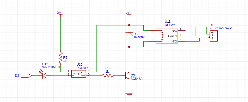
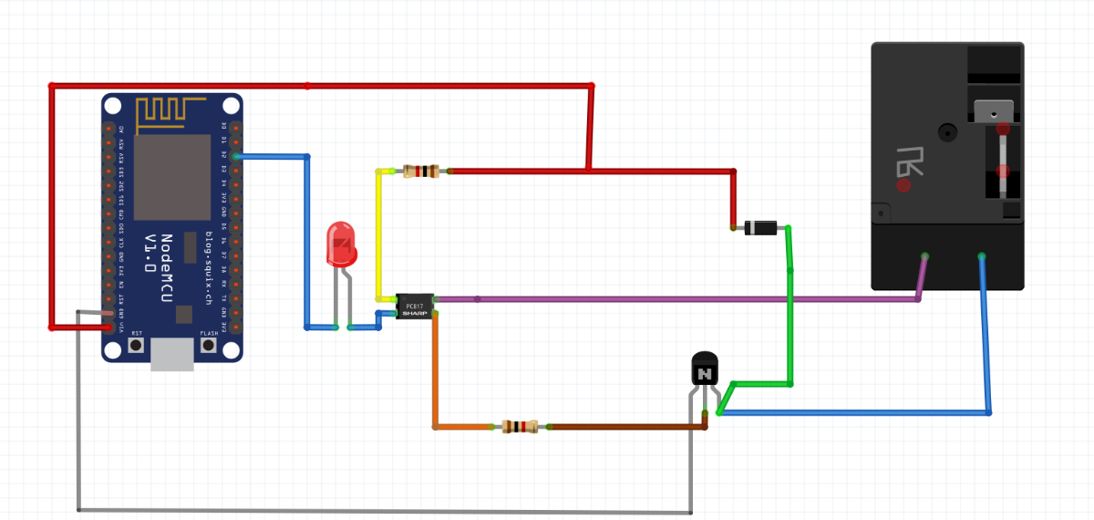
Make four such circuits and connect the anode of LED with D2, D5, D6, and D7 as mentioned in the above schematic. Make sure to connect the transistor properly. The driver circuit of relay is ready.
It uses an Optocoupler for insulation and transistor to switch the relays.
For the ease of it, I have also made a PCB for the circuit. The gerber files are uploaded along with. You can see how PCB will look below.
.png)
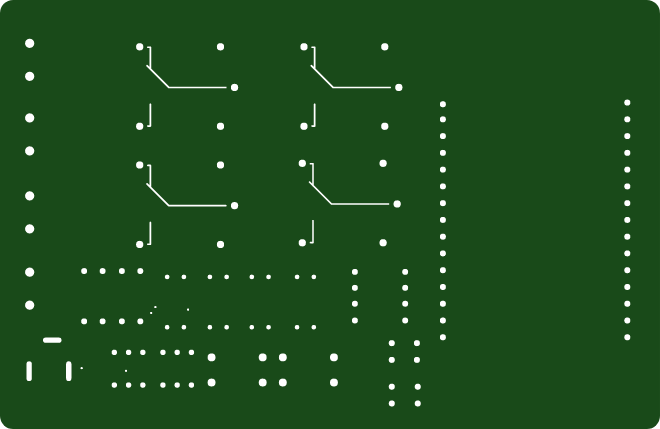
The manufactured PCB also looks very amazing. (Image Below)
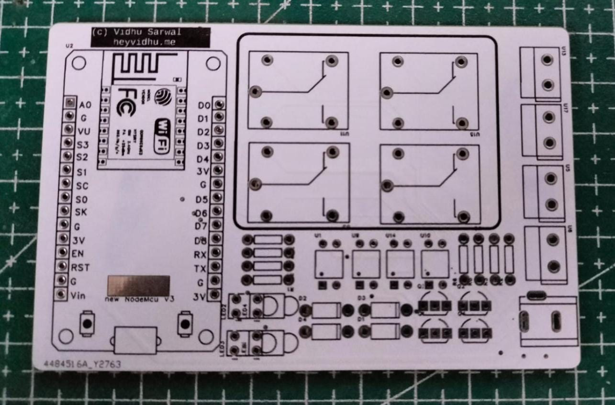
With this we are done with the circuitry part.
Part 2: Setting up NodeMCU and Program.
We will be using ESP8266 based NodeMCU for this. This chip comes with its own WiFi, so you won't have to use any external chip or wires for communication.
The code essentially does 2 things
- Control the pins D2, D5, D6, D7. When it is pulled Low, The relay switches on and when it is pulled High, the relay switches off.
- Host a website in the Wifi network to control the relay. I have kept this webpage in case there is any issue with the app and also for general testing.
But to upload the program to the MCU, you will need to set-up Arduino IDE as well.
Follow these steps to add esp to your arduino ide.
- Open the Arduino IDE.
- Go to File > Preferences.
- In the Additional Board Manager URLs field, add the following URL.
http://arduino.esp8266.com/stable/package_esp8266com_index.json
- Go to Tools > Board > Boards Manager.
- In the Boards Manager window, search for esp8266.
- Click on the esp8266 by ESP8266 Community and click Install.
- After that select the correct board and correct port.
Then copy and paste the below code.
// make sure to install these libraries although they come pre-installed.
#include <ESP8266WiFi.h>
#include <ESP8266WebServer.h>

// !!!IMPORTANT!!!!!  Replace with your network credentials
const char* ssid = "YOUR_WIFI";
const char* password = "YOUR_PASS";

// Create an instance of the server. This is why we are using ESP8266.
ESP8266WebServer server(80);

// Pin definitions. You maye edit them if you want.
const int relay1 = D6;
const int relay2 = D7;
const int relay3 = D2;
const int relay4 = D5;

bool relay1State = LOW;
bool relay2State = LOW;
bool relay3State = LOW;
bool relay4State = LOW;

void setup() {

  Serial.begin(115200);


  pinMode(relay1, OUTPUT);
  pinMode(relay2, OUTPUT);
  pinMode(relay3, OUTPUT);
  pinMode(relay4, OUTPUT);

  // Set relay pins to HIGH initially (relay off)
  digitalWrite(relay1, HIGH);
  digitalWrite(relay2, HIGH);
  digitalWrite(relay3, HIGH);
  digitalWrite(relay4, HIGH);

  // Connect to Wi-Fi. You can see this on serial monitor also to verify and know if connected.
  WiFi.begin(ssid, password);
  Serial.print("Connecting to ");
  Serial.print(ssid);
  while (WiFi.status() != WL_CONNECTED) {
    delay(500);
    Serial.print(".");
  }
  Serial.println("");
  Serial.println("WiFi connected");

  // Print the IP address
  Serial.println("IP address: ");
  Serial.println(WiFi.localIP());


  server.on("/", handleRoot);

// we can also use these hooks with the flutter app.
  server.on("/relay1/toggle", []() {
    relay1State = !relay1State;
    digitalWrite(relay1, relay1State ? LOW : HIGH);
    server.send(200, "text/plain", relay1State ? "Relay 1 ON" : "Relay 1 OFF");
  });
  server.on("/relay2/toggle", []() {
    relay2State = !relay2State;
    digitalWrite(relay2, relay2State ? LOW : HIGH);
    server.send(200, "text/plain", relay2State ? "Relay 2 ON" : "Relay 2 OFF");
  });
  server.on("/relay3/toggle", []() {
    relay3State = !relay3State;
    digitalWrite(relay3, relay3State ? LOW : HIGH);
    server.send(200, "text/plain", relay3State ? "Relay 3 ON" : "Relay 3 OFF");
  });
  server.on("/relay4/toggle", []() {
    relay4State = !relay4State;
    digitalWrite(relay4, relay4State ? LOW : HIGH);
    server.send(200, "text/plain", relay4State ? "Relay 4 ON" : "Relay 4 OFF");
  });

  // Start the server
  server.begin();
  Serial.println("HTTP server started");
}

void loop() {
  // Handle client requests
  server.handleClient();
}

void handleRoot() {
  // Below is our html content.
  String html = "<html><head>";
  html += "<style>";
  html += "body { font-family: Arial, sans-serif; text-align: center; }";
  html += ".switch { position: relative; display: inline-block; width: 60px; height: 34px; }";
  html += ".switch input { display: none; }";
  html += ".slider { position: absolute; cursor: pointer; top: 0; left: 0; right: 0; bottom: 0; background-color: #ccc; transition: .4s; }";
  html += ".slider:before { position: absolute; content: ''; height: 26px; width: 26px; left: 4px; bottom: 4px; background-color: white; transition: .4s; }";
  html += "input:checked + .slider { background-color: #2196F3; }";
  html += "input:checked + .slider:before { transform: translateX(26px); }";
  html += ".slider.round { border-radius: 34px; }";
  html += ".slider.round:before { border-radius: 50%; }";
  html += "</style></head><body>";
  html += "<h1>ESP8266 Smart IoT switch</h1>";
  html += "<label class='switch'><input type='checkbox' id='relay1' onchange='toggleRelay(\"relay1\")'><span class='slider round'></span></label> Relay 1<br><br>";
  html += "<label class='switch'><input type='checkbox' id='relay2' onchange='toggleRelay(\"relay2\")'><span class='slider round'></span></label> Relay 2<br><br>";
  html += "<label class='switch'><input type='checkbox' id='relay3' onchange='toggleRelay(\"relay3\")'><span class='slider round'></span></label> Relay 3<br><br>";
  html += "<label class='switch'><input type='checkbox' id='relay4' onchange='toggleRelay(\"relay4\")'><span class='slider round'></span></label> Relay 4<br><br>";
  html += "<script>";
  html += "function toggleRelay(relay) {";
  html += "  var xhr = new XMLHttpRequest();";
  html += "  xhr.open('GET', '/' + relay + '/toggle', true);";
  html += "  xhr.send();";
  html += "  xhr.onload = function() {";
  html += "    if (xhr.status === 200) {";
  html += "      console.log(xhr.responseText);";
  html += "    }";
  html += "  };";
  html += "}";
  html += "</script>";
  html += "</body></html>";

  // Send the HTML content to the client
  server.send(200, "text/html", html);
}
Upload this code to the ESP8266.
After the code is uploaded, reset the ESP and open serial monitor. You should be able to see the IP Address of ESP. Go that IP Address and you will see a page similar to one below.
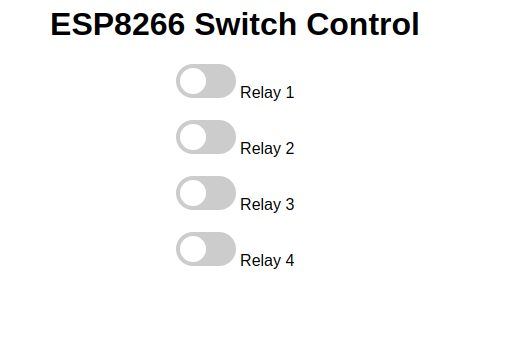
Now you will be able to control the board through website.
Now moving the part to make the flutter app.
Tip: Add the IP of ESP to static IP for ease later.
Part 3: Creating a Flutter App for Added Ease
Flutter is an easy to use framework to make multi-platform apps. You can make Windows, Android, iOS, MacOS and Linux apps through this.
However, For our project we are going to use it to make a simple app to control the switch board.
The first step is to have flutter setup and ready on your PC.
https://docs.flutter.dev/get-started/install
This is a really great guide to walk you through initial setup. Once you are done with this, Follow the below steps to build the app.
- Open any folder of your choice in which you want to make your app.
- Run
flutter create relay_control_app- now open the folder in the IDE win which you setup Flutter.
- Go to lib/main.dart and copy paste the below code.
import 'package:flutter/material.dart';
import 'package:http/http.dart' as http;

void main() {
  runApp(MyApp());
}

class MyApp extends StatelessWidget {
  @override
  Widget build(BuildContext context) {
    return MaterialApp(
      title: 'ESP8266 Relay Control',
      theme: ThemeData(
        primarySwatch: Colors.blue,
      ),
      home: MyHomePage(),
    );
  }
}

class MyHomePage extends StatefulWidget {
  @override
  _MyHomePageState createState() => _MyHomePageState();
}

class _MyHomePageState extends State<MyHomePage> {
  bool _relay1State = false;
  bool _relay2State = false;
  bool _relay3State = false;
  bool _relay4State = false;

  final String baseUrl = 'http://IP_ADDRESS'; // Replace with your ESP8266 IP address

  Future<void> _toggleRelay(String relay) async {
    final response = await http.get(Uri.parse('$baseUrl/$relay/toggle'));
    if (response.statusCode == 200) {
      setState(() {
        switch (relay) {
          case 'relay1':
            _relay1State = !_relay1State;
            break;
          case 'relay2':
            _relay2State = !_relay2State;
            break;
          case 'relay3':
            _relay3State = !_relay3State;
            break;
          case 'relay4':
            _relay4State = !_relay4State;
            break;
        }
      });
    } else {
      throw Exception('Failed to toggle relay');
    }
  }

  @override
  Widget build(BuildContext context) {
    return Scaffold(
      appBar: AppBar(
        title: Text('ESP8266 Relay Control'),
      ),
      body: Center(
        child: Column(
          mainAxisAlignment: MainAxisAlignment.center,
          children: <Widget>[
            SwitchListTile(
              title: Text('Relay 1'),
              value: _relay1State,
              onChanged: (bool value) {
                _toggleRelay('relay1');
              },
            ),
            SwitchListTile(
              title: Text('Relay 2'),
              value: _relay2State,
              onChanged: (bool value) {
                _toggleRelay('relay2');
              },
            ),
            SwitchListTile(
              title: Text('Relay 3'),
              value: _relay3State,
              onChanged: (bool value) {
                _toggleRelay('relay3');
              },
            ),
            SwitchListTile(
              title: Text('Relay 4'),
              value: _relay4State,
              onChanged: (bool value) {
                _toggleRelay('relay4');
              },
            ),
          ],
        ),
      ),
    );
  }
}
!!!!! IMPORTANT !!!!! - Add your IP_Address of ESP in the code.
- Now go to your pubspec.yaml file and add the below under dependencies.
dependencies:
  flutter:
    sdk: flutter
http: ^0.13.3 # Add this line- Now run
flutter pub get- And to debug the app enter
flutter runThat's It. Now you have got an app to control your smart Switch relay board. Connect it with anything you want.