This is very simple to build an Infrared Motion Detector using timer IC 555 and OpAmp. There is a different way to design and develop the Infrared Motion detector but this one is a very simple, easy to build, and inexpensive design, and low-cost PCB prototype built from JLC PCB.
JLCPCB (Shenzhen JIALICHUANG Electronic Technology Development Co., Ltd.), is the largest PCB prototype enterprise in China and a high-tech manufacturer specializing in quick PCB prototype and small-batch PCB production. With over 10 years of experience in PCB manufacturing, JLCPCB has more than 200, 000 customers at home and abroad, with over 8, 000 online orders of PCB prototyping and small quantity PCB production per day. The annual production capacity is 200, 000 sq.m. for various 1-layer, 2-layer, or multi-layer PCBs. JLC is a professional PCB manufacturer featured in large scale, well equipment, strict management, and superior quality.
Transmitter:
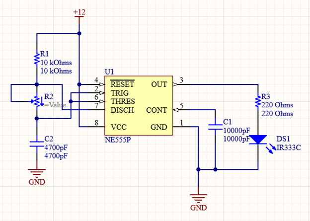
On the transmitter side, the IC 555 is used as an astable multivibrator to generate a 5kHz square wave frequency. At an output of IC 555, the IR Diode is connected to switch the IR Beat at a same frequency. These beams are picked by the infrared sensor, photo transistor Q1.
Receiver:
AT a receiver side the phototransistor L14F is used to catch the 5kHz frequency transmitted by the transmitter. At normal conditions, that is, when there is no intrusion the output pin (7) of IC2 will be low. When there is an intrusion the phase of the reflected waveforms has a difference in phase and this phase difference will be picked by the IC2. Now the pin 7 of the IC 2 goes high to indicate the intrusion. An LED or a buzzer can be connected at the output of the IC to indicate the intrusion.
Transmitter Circuit Diagram:
Receiver Circuit Diagram:
.png)
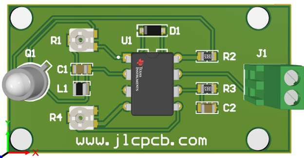
Transmitter Layout:
.png)
3D View
Receiver Layout:
.png)
3D View: