
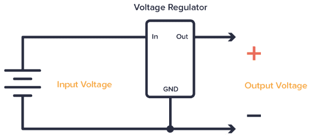
A voltage regulator is a component that converts a voltage to a lower (or higher) level.
An example of this is when making a portable USB charger and needing to use a 9V battery but also needing 5V in the circuit. Then, you can utilize a voltage regulator that produces a regulated 5V output from a 9V input for usage in your circuit.
Instead of having two power supplies, you can merely use one 12V supply and add one to provide the microcontroller with a 5V voltage regulator if you are designing a circuit that requires multiple voltage levels, such as one where the motors need 12V and the microcontroller need 5V.
How to connect the voltage regulator
To make the output more steady, you typically need to attach some additional components to the regulator. a minimum of one or two capacitors However, it depends on the regulator you pick. In the regulator's datasheet, you can find instructions on how to connect that particular regulator.
The voltage regulator 7805, for instance, is a popular model. You get a 5V output from it. You may find this sample circuit from the 7805 datasheet, which demonstrates the requirement for two capacitors:
.png)
Regulator Type
There are two common types of voltage regulators worth knowing about:
- Linear Regulator
- DC-DC switching regulator
The least complex regulators are linear ones, which just need a few capacitors and possibly a few resistors to function.
The linear regulators 7805 and LM317 with adjustable output voltage are two examples.
.png)
The operation of DC-DC switching regulators, which are a little more complex, depends on inductors and diodes. A more typical illustration is the LM2596. However, you can typically purchase these as compact modules with all the components you need on the board (search for DC-DC converters).
.png)
The primary distinction between the two is the amount of electricity wasted by switching regulators versus linear regulators. As a result, linear regulators can rapidly become quite warm if enough cooling is not provided.
Additionally, switching regulators are the only ones that can provide an output voltage greater than the input voltage. You will always get a lower output voltage from a linear regulator.
How Linear Regulators Work
There are many ways to design a linear regulator. This is probably one of the easiest ways:
.png)
The output is always equal to the transistor voltage minus the zener voltage of the diode. V is normally between 0.6 and 0.7 volts. As a result, the output from a 5.6V zener will be close to 5V.
V is going low if the output voltage is greater than 5V. The voltage will again drop as a result of the transistor reducing the current. If the output is less than 5V, the converse occurs.
How a Switching Regulator Works
The switching regulator is the other primary type. This voltage regulator uses inductors to transform the voltage in a more energy-efficient manner while turning the input voltage on and off.
Generally, there are 3 types:
- Buck Converters – Converts to Lower Voltages
- Boost Converter – Converts to higher voltages
- Buck-Boost Converters – Converts to Lower and Higher Voltages
Here are the basic concepts of a buck converter:
.png)
Current from the battery travels via the inductor, capacitor, and load when the switch is pressed. The capacitor and inductor are both charged. The energy held in the capacitor and inductor is released when the switch is opened, supplying current to the load.
In actuality, transistors take the place of switches. Additionally, a detection system monitors the output voltage and determines whether to switch the transistor on and off more quickly (for higher voltage) or more slowly (for lower voltage).