The CAN bus terminal typically has a resistance of 120 ohms, see easybom. There are typically two 120 ohm nodes on the bus, and two 60 ohm resistors are connected in series in the design. Basically, individuals, who are accustomed to the CAN bus system It is well known that this.
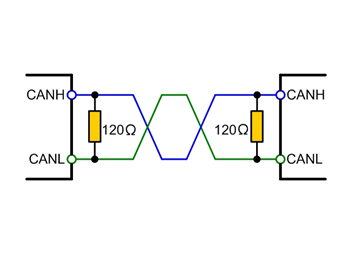
As an author, I am well aware that this resistance value is frequently used in various standards, data sheets, and application notes, but what do these two terminal resistors' functions entail? What does matching entail? Impedance matching has been explored previously.
This article's knowledge summary includes the following information. Knowing the function of the terminal resistor in everyday work may enable you to identify a problem's root cause earlier, such as unstable waveforms.
Terminating resistors' function
There are three functions of the CAN bus terminal resistor:
By allowing high-frequency and low-energy signals to fade away quickly, anti-interference performance is improved.
Make sure that the bus enters the recessive condition fast so that the energy of the parasitic capacitance can dissipate more quickly.
In order to decrease reflected radiation and improve signal quality, place these at both ends of the bus.
Boost anti-interference performance
The CAN transceiver determines the "dominant" and "recessive" states of the CAN bus. "Dominant" stands for "0," and "recessive" for "1." The diagram below depicts the internal layout of a CAN transceiver, with CANH and CANL connected to the bus.
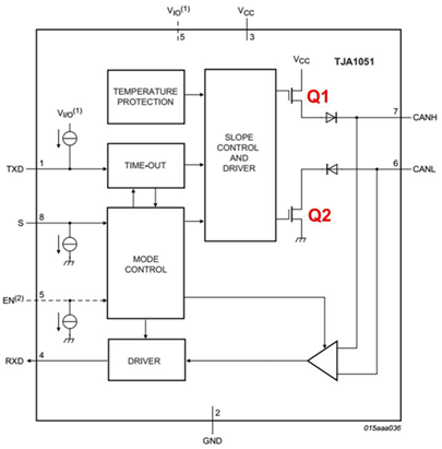
When the bus is dominant, the transceiver's Q1 and Q2 are turned on, creating a pressure difference between CANH and CANL; when the bus is recessive, the transceiver's Q1 and Q2 are turned off, placing CANH and CANL in a passive state with no pressure difference; and when the bus is dominant, the transceiver's Q1 and Q2 are turned off, creating no pressure difference between CANH and CANL.
The internal MOS tube is in a high-impedance condition when there is no load on the bus and the differential resistance value is very high. The bus can reach dominant mode with relatively little energy from external disturbance (the minimum voltage of the common transceiver dominant threshold). (Just 500mV) There will be obvious fluctuations on the bus if differential mode interference is present, and since there is nowhere for these fluctuations to go, a dominant bit will form on the bus as a result. In order to strengthen the bus's anti-interference capabilities while it is recessive, a differential load resistor can be added. Its resistance value should be as low as practical to minimize the impact of most of the noise energy. To avoid requiring too much current from the bus to become dominant, the resistance shouldn't be too low.
Making sure the recessive state enters quickly
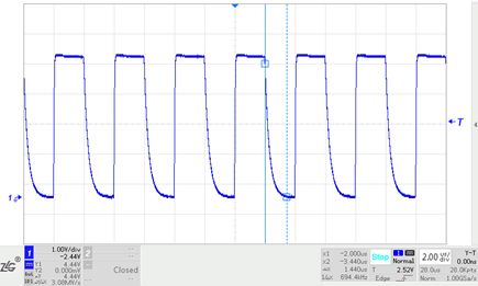
When the bus switches back to the recessive state from the dominant state, the parasitic capacitances on the bus must be discharged. If there is no resistive load provided between CANH and CANL, the capacitor can only be discharged through the differential resistance inside the transceiver. This impedance is really high. Due to the characteristics of the RC filter circuit, the discharge time will be significantly longer. We use a 220PF capacitor to connect the CANH and CANL of the transceiver in the simulation test. It has a 500 kilobits per second bit rate. The diagram displays the waveform. The falling edge of this waveform represents a somewhat prolonged state.
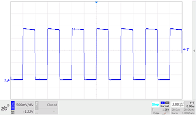
In order to quickly discharge the bus' parasitic capacitance and ensure that the bus enters the recessive condition, a load resistor must be connected between CANH and CANL. The diagram shows the waveform after a 60 ohm resistor has been added. As seen in the figure, the time from dominant recovery to recessive is shortened to 128nS, which is comparable to the dominant settling period.
Boost the signal's quality
Signal reflection happens when a signal's edge energy encounters an impedance mismatch at a rapid slew rate. If the cross-sectional geometry of a transmission cable changes, the cable's characteristic impedance also changes, causing reflections.
When energy is reflected, the reflected waveform is superimposed on the original waveform, producing ringing.
The bus signal rings as a result of the abrupt change in impedance at the bus cable's termination, which causes energy reflection of the signal edge. If the ringing amplitude is too high, the quality of the transmission will suffer. This portion of the energy can be absorbed and ringing prevented by a terminal resistance at the cable's termination that is equivalent to the characteristic impedance of the cable.
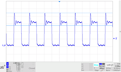
The transceivers CANH and CANL are connected to a twisted pair that spans about 10 meters, and the data rate is 1 Mbit/s. To ensure recessive conversion time, the transceiver is terminated with a 120 resistor and the end is not loaded. The graphic shows the waveform of the signal at the end, and the rising edge of the signal has ringing.
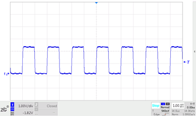
The signal waveform much improves and the ringing goes away when a 120 resistance is put to the twisted pair's end.
A termination resistor needs to be attached to each end of the cable since in a linear topology both ends of the cable serve as the transmitting and receiving ends.
In actual application processes, the CAN bus is often a combination of the bus and the star and is not a perfect bus design. It mimics the typical architecture of the CAN bus.
Why do you want 120?
Impedance: What precisely is it? Impedance in electrical terms refers to a circuit's resistance to current flow. The ohm, which is sometimes represented as Z and is a complex number with the formula Z=R+i(L-1/(C)), is the unit of impedance. Resistance, which is the actual component of impedance, and reactance, which is the conceptual part, are separated (imaginary part). The reactance includes capacitive and inductive reactances. The current obstruction generated by capacitance is known as capacitive reactance, whereas the current obstruction induced by inductance is known as inductive reactance. The Z mode is referred described as having "impedance."
Experimental analysis can establish the characteristic impedance of every cable. An oscilloscope is used to view the waveform on the adjustable resistor connected to the cable, which is connected to a square wave generator on one end and a square wave generator on the other. When the signal on the resistor is a good square wave without ringing, adjust the resistor's resistance value until it is consistent with the cable's characteristic impedance.
Using two conventional automobile cables and twisting them into twisted pairs as described above, the characteristic impedance may be calculated. This impedance is approximately 120, which is also the resistance value of the terminal resistance advised by the CAN standard, therefore this 120 is measured. It isn't computed; instead, it is determined by the characteristics of the actual wiring harness. Of course, it is also defined under the ISO 11898-2 standard.

Why is 0.25W the power of choice?
This needs to be calculated along with several fault situations. In accordance with the standard, the short-circuit of the CAN bus node to the power supply as well as the short-circuit to 18V must be taken into account in addition to the short-circuit to the power supply and the short-circuit to the ground in all interfaces of the vehicle ECU. If CANH is shorted to 18V, current will flow to CANL through the terminating resistor. The maximum injection current inside CANL is 50mA (stated in the TJA1145) due to current limiting, and the current flowing through the 120 resistor at this time is 50mA. *50mA*120Ω=0.3W. The power of the terminal resistor is 0.5W, however it degrades at high temperatures.
