
Why is there such a large ripple in your power supply?
Introduction to ripple
Because the AC power supply often creates the DC stable power supply through rectification, voltage regulation, and other links, it is unavoidable that there will be some AC components in the DC stable amount. This kind of THE AC component superimposed over the DC stable amount is known as ripple. The ripple wave's composition is more intricate, and compared to a similar sinusoidal harmonic wave, its frequency is typically higher. The other wave type is a pulse wave with an extremely small breadth. The requirements of ripple vary depending on the situation.
Effective value, peak value, absolute value, and relative value are all ways to represent ripple. (According to Easybom) For instance, in a power supply operating in a stable voltage condition, the output is 100V at 5A, the measured ripple effective value is 10mV, the absolute amount of ripple is 10mV, and the relative amount is 10mV divided by 100V, or 0.01%, or 1/10,000.
The reason the power supply ripple so big
The peak-to-peak value of ripple and noise was found to be more than 900 mV when a user tested the ripple of a 5V signal output from his switching power supply with a 500MHz bandwidth oscilloscope, while the peak-to-peak value of the nominal ripple of his switching power supply was 20mV (as shown in the figure below). Although there is an LDO on the user circuit board's backstage to regulate the switching power supply's output voltage. The user wants to identify the issue because they believe the measured result is too huge and unreliable.
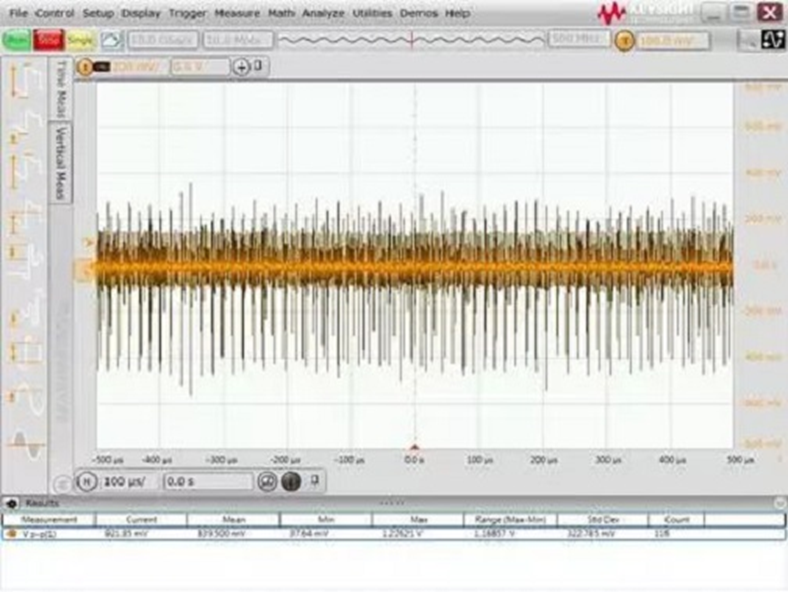
Figure. 1
Analysis of the issue
The probe being used and how the front end is connected are typically the issues with significant power ripple tests. First, the user probe's connection mode was examined. It was discovered that the ground point was clamped on the fixed screw of the single board and that the lengthy crocodile clip ground wire was employed, as indicated in the left image below. The size of the entire ground loop was considerable. Due to the switching power supply's ground loop noise and the larger ground loop's increased electromagnetic radiation noise in space. As seen in the right figure below, the short ground spring pin is changed.
.jpeg)
Figure. 2
Following actual testing, it was discovered that the measured ripple noise's peak-to-peak value had significantly increased, as can be seen in the figure below. The switch power supply manufacturer's nominal 20mV is still a significant discrepancy, and the ripple noise peak-to-peak value is still over 40 mV.
.jpeg)
Figure. 3
Further investigation into the user's probe model revealed that the oscilloscope standard with 10:1 passive probe was being used. as seen in the following diagram.
.jpeg)
Figure. 4
The 10:1 probe will 10 times attenuate the observed signal before feeding it into an oscilloscope, which will 10 times mathematically amplify it. The benefit of this probe is that the front matching circuit improves the probe bandwidth to several hundred MHz and broadens the oscilloscope's field of view, but it is not very advantageous for measuring tiny signals. Even with another 10 times of mathematical amplification, if the measured signal amplitude is minimal, the signal-to-noise ratio will not be increased and another 10 times of attenuation may be lost in the oscilloscope noise. As a result, it is recommended to use a probe with a low attenuation ratio, such as a 1:1 probe, for measuring power ripple noise. So, another 1:1 passive probe is discovered. This 1:1 passive probe has a tiny attenuation ratio and a low bandwidth (often several MHz), making it ideal for testing small signals.
The comparison test results of the 1:1 passive probe and the 10:1 probe for various bandwidth constraints are shown in the following figure. It can be seen that the measured ripple noise peak-to-peak value is less than 10mV after using a 1:1 probe and establishing a 20MHz bandwidth restriction, which is significantly better than the test result of a 10:1 probe. According to the test results of the 1:1 probe, the ripple waveform is clear and the user's expected level of power ripple noise is 20 mV. In addition, we can observe that the noise peak-to-peak value is somewhat improved by the bandwidth limit.
.jpeg)
Figure. 5
Problem outline
This power ripple test issue is common. By using a short ground connection, switching to a probe with a low attenuation ratio, and bandwidth limiting, we have significantly improved the ripple noise test findings. In general, the following factors are important and have an impact on power ripple test results:
1. The front end of the connection line and the length of the ground loop: A long ground loop will pick up more electromagnetic radiation and ground noise from switching power supplies, so it is necessary to choose a ground connection that is as short as feasible.
2. Probe attenuation ratio: Try to use a 1:1 attenuation ratio for the probe because a larger attenuation ratio would make the little signal amplitude weaker and even masked by oscilloscope noise.
3. Bandwidth limit: Because oscilloscope noise and a lot of electromagnetic noise are broadband, setting the right bandwidth limit can help to reduce unwanted noise. While certain processors demand a bandwidth limit of 80MHz or 200MHz, many power ripple noise testing applications employ a bandwidth limit of 20MHz.
4. Measuring range: For power ripple tests, a modest range is typically used (for example, 10MV/grid or 20mV/grid). The oscilloscope's noise level increases with range size. The detected DC voltage signal may not be able to be pulled back to the center of the screen for measurement at a little tap, though, because certain oscilloscopes have a constrained range of bias. Therefore, the DC is commonly isolated using the oscilloscope's AC coupling feature before a ripple noise test is run.
5. Input impedance: 50 ohm and 1 M ohm input impedance options are available on many oscilloscopes; 50 ohm input impedance oscilloscopes often have lower bottom noise. However, when the oscilloscope is linked to the majority of passive probes, the impedance is automatically changed to 1M ohm, and the input impedance may only be modified to 50 ohm when the active probe or coaxial cable is connected.
Before performing actual tests, it is a good idea to examine the background noise of the present device and system settings. The bottom noise results of a 500M S series oscilloscope with various probe and bandwidth settings are represented by the five waveforms in the image below. Waveform: 50 ohm input impedance, 1:1 probe, 500 MHz bandwidth; 1M ohm input impedance, 1:1 probe, 20 MHz bandwidth; 1M ohm input impedance, 1:1 probe, 500 MHz bandwidth; 1M ohm input impedance, 10:1 probe, 20 MHz bandwidth; The bottom noise's peak-to-peak value ranges from less than 1 mV to about 30 mV, emphasizing the significance of the probe, bandwidth, and input impedance settings in the test.
.jpeg)
Figure. 6
You can also create a handmade probe using 50 ohm coaxial cable if you really don't have access to a suitable low attenuation ratio probe. The central conductor is connected to the power signal under test through a straight capacitor, and the shield layer is welded to the ground of the circuit under test. In practice, one end of the cable is connected to an oscilloscope set to 50 ohm input impedance. The other end of the cable is peeled off. Inexpensive attenuation ratio and low cost are its advantages, but inconsistent results and poorly regulated isolated capacitance and bandwidth parameters make this method less reliable.Additionally, oscilloscope manufacturers have introduced probes specifically made for power ripple testing in recent years. These probes feature low attenuation ratio (1.1:1), high bandwidth (hardware 2GHz, software-set bandwidth limit), impedance matching for measurement needs and noise (the probe's dc input impedance is 50K ohm, but the oscilloscope end is 50 ohm input impedance spectrum), short ground wire (offers very low loop inductance welding front), wide bias range (up to 24V), and simultaneous testing of ripple and DC voltage make it appropriate for users with reasonably high power ripple measuring needs.
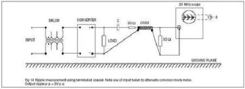
Figure. 7