EQUIPMENTS REQUIRED
- ARDUINO UNO:- The Arduino Uno is an open source microcontroller board based on the Microchip ATmega328P microcontroller. The board is equipped with sets of digital and Analog I/O pins that may be interfaced to various expansion boards (shields) and other circuits. The board has 14 digital I/O pins (six capable of PWM output), 6 Analog I/O pins, and is programmable with the Arduino IDE (Integrated Development Environment), via a type B USB-cable. It can be powered by the USB cable or by an external 9- volt Battery, though it accepts voltages between 7 and 20 volts. The ATmega328 on the board comes pre-programmed with a bootloader that allows uploading new code to it without the use of an external hardware programmer. The Uno communicates using the original STK500 protocol, it differs from all preceding boards in that it does not use the FTDI USB-to-serial driver chip. Instead, it uses the Atmega16U2 (Atmega8U2 up to version R2) programmed as a USB-to-serial convertor. The Arduino Uno has a number of facilities for communicating with a computer, another Arduino board, or other microcontrollers. The ATmega328 provides UART TTL (5V) serial communication, which is available on digital pins 0 (RX) and 1 (TX). An ATmega16U2 on the board channels this serial communication over USB and appears as a virtual com port to software on the computer. The 16U2 firmware uses the standard USB COM drivers, and no external driver is needed. However, on Windows, a .inf file is required. Arduino Software (IDE) includes a serial monitor which allows simple textual data to be sent to and from the board. The RX and TX LEDs on the board will flash when data is being transmitted via the USB-to-serial chip and USB connection to the computer (but not for serial communication on pins 0 and 1). A Software Serial library allows serial communication on any of the Uno's digital pins.
.png)
- ULTRASONIC SENSOR (HCSR04):-The HC-SR04 Ultrasonic (US) sensor is a 4-pin module, whose pin names are VCC, Trigger, Echo and Ground respectively. This sensor is a very popular sensor used in many applications where measuring distance or sensing objects are required. The module has two eyes like projects in the front which forms the Ultrasonic transmitter and Receiver.
The sensor works with the simple formula that;
Distance = Speed × Time
The Ultrasonic transmitter transmits an ultrasonic wave, this wave travels in air and when it gets objected by any material it gets reflected back toward the sensor this reflected wave is observed by the Ultrasonic receiver module. Now, to calculate the distance using the above formulae, we should know the Speed and time. Since we are using the Ultrasonic Wave we know the universal speed of US wave at room conditions which is 340m/s. The circuitry inbuilt on the module will calculate the time taken for the US wave to come back and turns on the echo pin high for that same particular amount of time, this way we can also know the time taken. Now simply calculate the distance using a microcontroller or microprocessor.
.png)
.png)
- TOWERPRO SERVO MOTOR (SG90):- It is tiny and lightweight with high output power. This servo can rotate approximately 180 degrees (90 in each direction), and works just like the standard kinds but smaller. We can use any servo code, hardware or library to control the servo motor. This servo motor finds many applications in areas which require a 180 motion of light weight objects. Highly used in many robotic projects that require Pan-Tilt mechanisms for Cameras Ultrasonic Sensors etc. This motor can also be used to make light weight and small-sized bipeds, humanoids, spiders (6- or 8- legged), robot hand, robot arm and other similar applications. This motor has 3 pins- middle wire (red) connects to VCC, brown wire connects to GND, and yellow wire is signal which is to be connected to the digital pin of the Arduino board. It is usually a good idea to power the motors from an external power source and not directly from the Arduino board. When powering the motor from the external source, it is important to remember to create a common ground, by connecting the GND of the source with the GND pin of the Arduino board. As we know there are three wires coming out of this motor. The description of the same is given on top of this page. To make this motor rotate, we have to power the motor with +5V using the Red and Brown wire and send PWM signals to the Orange colour wire. Hence we need something that could generate PWM signals to make this motor work, this something could be anything like a 555 Timer or other Microcontroller platforms like Arduino, PIC, ARM or even a microprocessor like Raspberry Pie. The PWM signal produced should have a frequency of 50Hz that is the PWM period should be 20ms. Out of which the On-Time can vary from 1ms to 2ms. So when the on-time is 1ms the motor will be in 0° and when 1.5ms the motor will be 90°, similarly when it is 2ms it will be 180°. So, by varying the on-time from 1ms to 2ms the motor can be controlled from 0° to 180°.
.png)
- PIC18F4431 MICROCONTROLLER:- The PIC18F4431-I/P is a high[1]performance PIC18 family 8-bit powerful (200 nanosecond instruction execution) yet easy-to-program CMOS flash-based Microcontroller packs powerful PIC (RISC) architecture with up to 16 MIPS of processing power. This product offer all of the advantages of the well-recognized high performance x16 architecture with standardized features including 16kB of addressable program memory size, 768bytes of data memory size, 36 general-purpose I/O pins9-channel 10-bit Analog-to-digital (A/D) converter. This device operates at a maximum frequency of 40MHz wide operating voltage of 2 to 5.5V.
.png)
SOFTWARES USED
- ARDUINO IDE:- For programming the microcontrollers in the Arduino board, the Arduino project provides an integrated development environment (IDE) makes it easy to write code and upload it to the board. It runs on Windows, Mac OS X, and Linux. The program is written in Arduino Programming language.
.png)
- PROCESSING:- Processing is an open source computer programming language and integrated development environment (IDE) built for the electronic arts, new media art, and visual design communities with the purpose of teaching the fundamentals of computer programming in a visual context. We use Java language to write programs within this software.
.png)
- MPLAB X IDE
- MPLAB DRIVER
- MPLAB COMPILER C18
- For uploading data into PIC18F4431 microcontroller board we use a device called ICD 3 (known as In-circuit Debugger).
.png)
WORKING
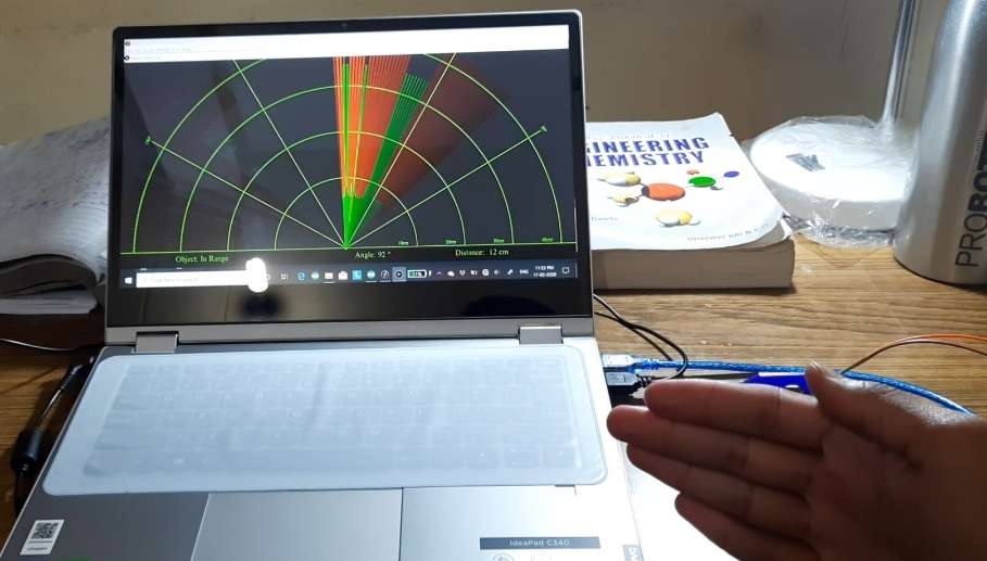
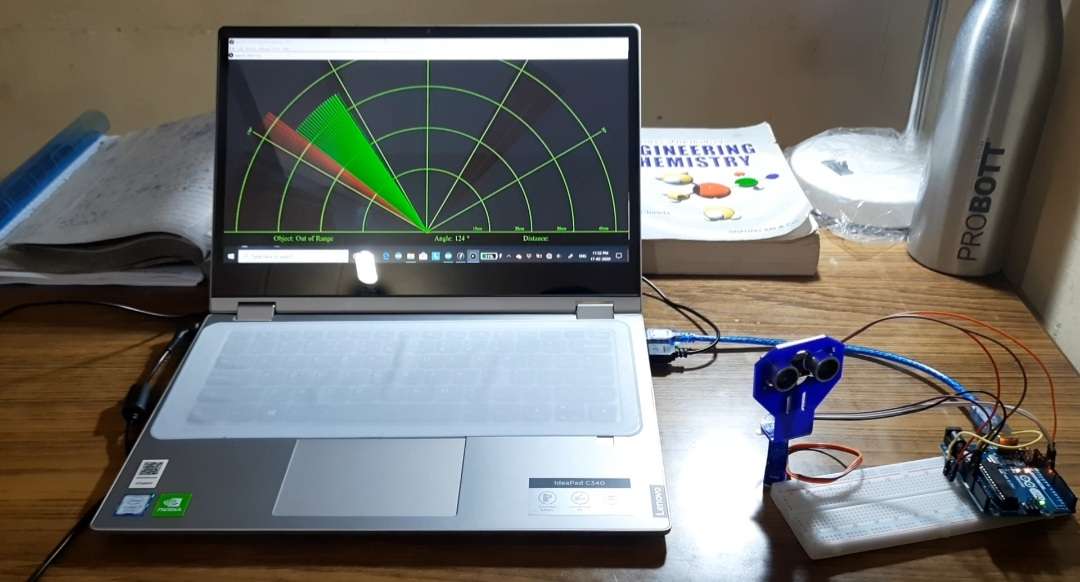
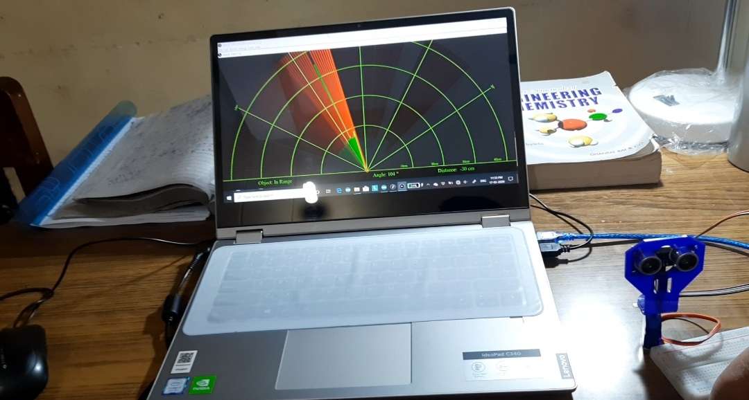
- FOR ARDUINO UNO:- Arduino board sends a signal of +5V to trig pin of Ultrasonic Sensor HC-SR04 which triggers the sensor. Then it provides rotational action at the servo motor mechanically fitted along with ultrasonic Sensor HC-SR04 so that it can detect the moving objects and locate within 180 degrees. The Arduino board sends a HIGH pulse width of (10 S) on the TRIGGER pin of the sensor to regenerate a series of ultrasonic waves which propagate through the air, until it touches an obstacle and returns in the opposite direction towards the sensor pin ECHO. The sensor detects the width of the pulse to calculate the distance. The signal on pin ECHO the sensor remains at the HIGH position during transmission, thereby measuring the duration of the round trip of ultrasound and thus determine the distance. The laptop screen displays the calculated distance and the angle of rotation.
- FOR PIC18F4431 MICROCONTROLLER:- The basics of servo interface is the pulse width, total working of the servo motor is controlled by the pulse width for different pulse width the servo motor rotate in different directions for a pulse width of 1us it is at 0 degree, for a pulse width of 1.5us it is at 90 degree and for a pulse width of 2us it is at 180 degree and we do the same for the reverse order also we should remember that the total time period should not exceed than 20us. We write the program for servo motor in MPLAB X IDE using embedded C language, and then use a device called ICD 3 to upload the program to the pic microcontroller board. The basics of the interface is very simple we make a delay of 10us so that the trig pin of the ultrasonic sensor gets activated (high) for which it sends 8 sonic bursts of 40khz then we have to activate the eco pin so that it reads the returning pulse. The way of detection is very simple we use a led that glow when there is no obstacle in front of the ultrasonic sensor but stops glowing when there is an obstacle placed in front of the ultrasonic sensor. We write the program for ultrasonic sensor in MPLAB X IDE using embedded C language, and then use a device called ICD 3 to upload the program to the pic microcontroller board.
RESULTS
CONCLUSION
We come across situations where we need to keep a watch over prohibited areas to avoid trespassing. Now keeping human labor for this purpose is costly and also not reliable for keeping a watch over an area 24×7. So, for this purpose an ultrasonic radar project for unauthorized human / animal or object detection system. The system can monitor an area of limited range and alerts authorities. For this purpose, we use a microcontroller circuit that is connected to an ultrasonic sensor mounted on a servo motor for monitoring. We also interface a LED for monitoring the detection status. The radar keeps monitoring the environment checking the ultrasonic sensor echo. As soon as an object is detected the data of detection is processed and sent to authorities with an alert of where exactly the object was detected. Thus, ultrasonic radar proves to be a very useful system for 24×7 monitoring of a particular area/region. The main application of the project is to keep watch 24*7 on prohibited areas to avoid trespassing is a difficult task. Keeping manual help is cost effective and not reliable too for keeping a watch over an area. The PIC Based Ultrasonic Radar System solves the problem. This system detects any unauthorized human/animal in the surrounding. The system monitors the area in the range and alerts the authorities. The PIC microcontroller in the circuit which is connected to an ultrasonic sensor mounted or servo motor for monitoring, glows the LED to notify the unauthorized identity.