


EXISTING METHODOLOGY:
In the existing methodology, a manual mushroom cultivation is made and it
requires optimum parameters for its growth, so it cannot be cultivated in different
location. Continuous monitoring of plant is required, so this kind of maximum
attention inhibits the multi-crop cultivation methodology. High yield is required to
meet the market needs and for that rapid production with minimal wastage, also
good quality and taste is required to gain high profit.
PROPOSED METHODOLOGY:
In the proposed methodology, we have used advanced heating system for
sterilization of hay in the initial growth of a required plant and cooling system for
maintaing the overall condition of the cabin. A low-power wide-area network
[LoRa] modulation technique for communication and data transfer which is
exclusively recommended in remote locations. By acquiring the data from the
system, the actuation part can be operated in a faster, more reliable with accuracy.
We have created our own mobile application and web page for visualization. By
using the retrieved data from the system data prediction for increased yield could
also be determined and the acquired sales data could also be used for forecasting
the upcoming sales with the help of smart machine learning algorithm.
HARDWARE REQUIREMENTS:
1.1 ACRYLIC SHEET:
The acrylic sheets are shown in Figure 4.1 have been utilized for this project
and they are of the dimensions 400 x 600 mm, 450 x 650 mm. The thickness of the
acrylic sheet is 5 mm. It is used as the base for the platforms and the adjacent
closure of the prototype. This material has been used as it is water-resistant and
gives an aesthetic look with great visibility.

Figure 4.1
L-CLAMP
The L-clamps used are shown in Figure 4.2. They are durable and versatile.
They are made up of high-quality aluminum. The dimensions of the L-clamp are 20
x 20 mm and can be utilized for locking the acrylic sheets of 400 x 600 mm, 450 x
9
650 mm. These are straight angle corner stand with two 8.8 x 5.9 mm oval holes
(+/- 0.05% Accuracy).

Figure 4.2
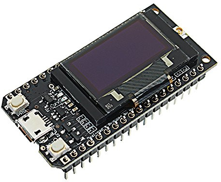
TTGO LoRa32
TTGO LoRa used in this system is shown in Figure 4.3. The Micro-
controller used in TTGO LoRa32 is ESP32. It is similar to the Arduino
development board but it differs from the connectivity criteria, so we choose this
module for wireless communication. This board has an inbuilt LoRa chip for
transmitting and receiving the small data packets and also has an SSD1306 0.96-
inch OLED display. LoRa has a high-frequency range compared to cellular
networks and it can be used by public, private and even private sectors too. The
module consists of Espressif ESP32, Semtech SX1276 an OLED display. This
module has high-resolution ADCs, SPI, I2C, and UART communication protocols.
As this module has an inbuilt OLED display it is internally connected to ESP32
through SDA pin of OLED is connected to GPIO 4 of ESP32, SCL pin is
connected to GPIO 15 of ESP32, RST pin is connected to GPIO 16 of ESP32, and
OLED display communicates with ESP32 through an I2C communication
protocol. As above said this module has an inbuilt SX1276 LoRa chip and it is
internally connected to ESP32 through the MISO pin of LoRa is connected through
10
GPIO 19 of ESP32, MOSI pin of LoRa is connected through GPIO 27 of ESP32,
SCK pin of LoRa is connected through GPIO 5 of ESP32, CS pin of LoRa is
connected through GPIO 18 of ESP32, IRQ pin of LoRa is connected through
GPIO 27 of ESP32 and RST pin of LoRa is connected through GPIO 14 of ESP32.
Figure 4.4 represents the pinout configuration of TTGO LoRa32. This module is
used the primary control board for monitoring the required parameters for
mushroom cultivation.
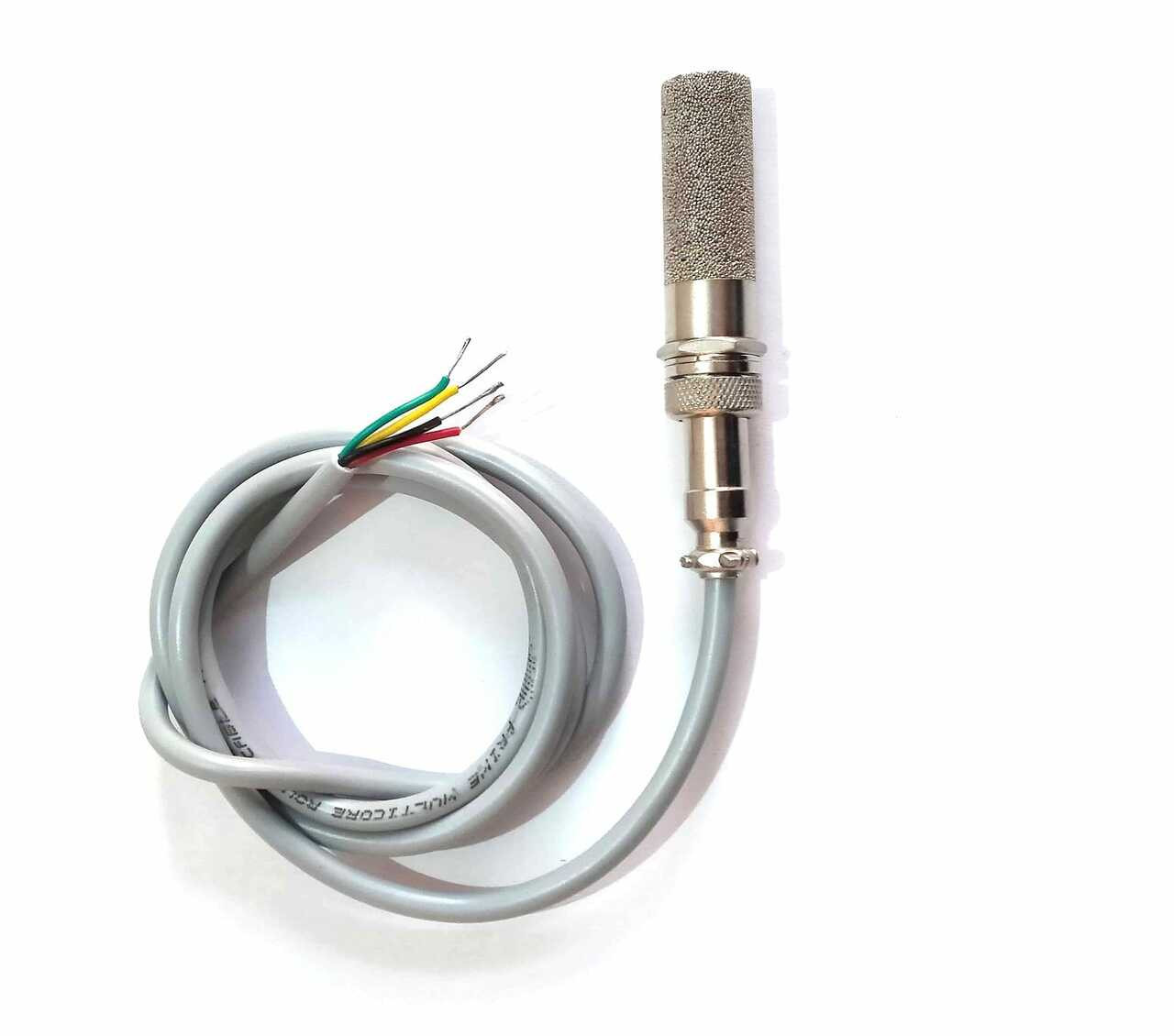
SHT20 SENSOR
The SHT20 sensor has been used to measure the temperature and relative
humidity inside the mushroom shed and it is shown in Figure 4.5. This sensor
module is of industry standard in the terms of form factor and intelligence. The
SHT20 sensor chip is embedded in a reflow solderable (DFN) leads which is in the
footprint size of 3 x 3 mm and the height is 1.1 mm. This sensor module
communicates in I2C digital, PWM, SDM format. The SHT20 sensors contain a
capacitive type humidity sensor and a bandgap temperature sensor. This yields an
unmatched sensor performance in the terms of accuracy, stability, low power
consumption, DFN type package – reflow solderable, and minimal power
consumption. The supply voltage is 2.1V – 3.6V, relative humidity (RH) response
time is 8 sec (tau63%), RH operating range is 0-100% RH and temperature
operating range is -40oC to +125oC. This sensor module is equipped with a
waterproof probe and that probe had undergone a dual waterproof protection test.
BH1750 SENSOR
The BH1750 sensor has been used to measure the light intensity inside the
mushroom shed and it is shown in Figure 4.6. This sensor uses an I2C
communication protocol and can be easily interfaced with any controllers. This
sensor use photodiode to sense the light and the PN junction are present in the
photodiode. The electron-hole pairs are created in the depletion region when the
light falls on it and electricity is produced in the depletion region due to the effect
of internal photoelectric. The electricity is produced in the depletion region is
proportional to the intensity of light and it is changed into an equivalent voltage
with help of Opamp. This sensor has inbuilt Opamp, OSC (clock oscillator of
320kHz), and ADC which convert the produced analog values by AMP into
equivalent digital values. Figure 4.7 represents the block diagram of the BH1750
sensor. The logic+I2C block shown in Figure 4.7, is the unit where the illuminance
values are converted to LUX. The supply voltage is from 2.4V to 3.6V and
requires 3.3V for working. So, voltage regulation an inbuilt voltage regulator is
there. The SDA and SCL are used for I2C communication, SCL is used to provide
clock pulse for I2C communication between the sensor and the controller, SDA is
used to transfer the data from the sensor to the controller.

MQ135 SENSOR
To measure the amount of CO2 inside the mushroom shed the MQ135
sensor has been used and it is shown in Figure 4.8. This sensor consists of a steel
exoskeleton and the sensing element is housed under the exoskeleton. The sensing
unit is made up of tin oxide, so the conductivity is lesser when air is clean and the
conductivity increases when the air gets polluted or venomous gas is detected.
This sensor is good sensitivity to harmful gases and has a long life compared to
other gas sensors. The operating voltage is from 0V to 5V and has two outputs,
i.e., analog and TTL output.

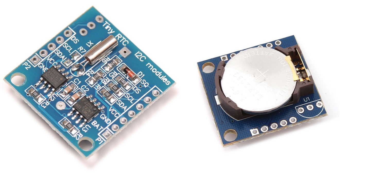
RTC DS1307 MODULE
The DS1307 RTC module has been used to monitor the time stamp and it is
shown in Figure 4.9. This module has 8 pin IC and it uses an I2C communication
protocol. The operating voltage is 3.3V to 5V and has 56 bytes of SRAM for
battery backup to run even there is no power supply.
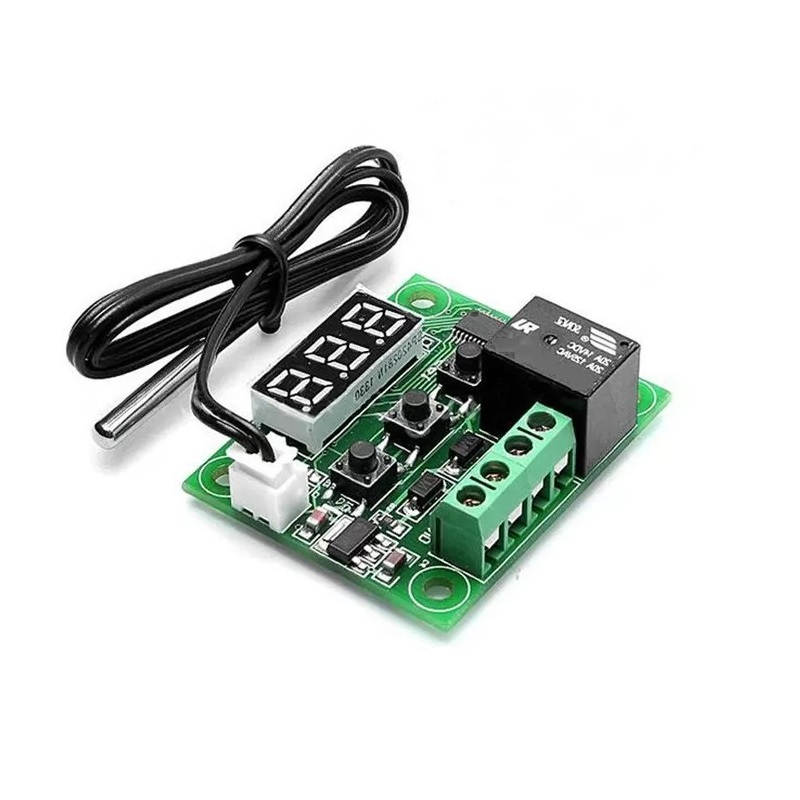
W1209 SENSOR
To measure the temperature outside the mushroom shed the W1209
temperature sensor module has been used and it is shown in Figure 4.10. This
sensor has a high functional thermostat controller and has high accuracy NTC
temperature sensor. This is module inbuilt module that can switch up to a
maximum of 240V AC at 5A or 14V DC at 10A and a 3-digit seven-segment
display that displays the temperature. The supply voltage is 12V DC.
RELAY MODULE
For switching purposes in this project, 4 channel relay modules have been
used and it is shown in Figure 4.11. This module can control high-power devices
up to 10A by giving high/low signals through any microcontroller and has an LED
indicator for on/off feedback. The supply voltage for this module is 5V DC.

PUMP
The water pump has been used to pump the water and spray it inside the
mushroom shed. This is an electric diaphragm water pump with auto cutoff and
self-priming. This pump has a flow rate of 4.5 liters/minute, a pressure of 110psi,
and a thermal overload protector. The operating voltage of this pump is 12V DC.
The inlet and outlet of this pump are 8 mm. Figure 4.12 represents the water pump
used in this project.
NOZZLE
To spray water inside the mushroom shed, the nozzle has been used and it is
shown in Figure 4.13. The inlet of this nozzle is 8 mm and the body is made up of
steel, to prevent rusting the brass coating is given to the outer layer.
.png)
HEATER
For sterilization of hay, the heating system is used in this project as shown
in Figure 4.14. The operating voltage of this heater is 230V DC & 1000W. This
heater has a hanging holder to prevent a short circuit and has a led for on/off
indication.

LED LIGHT
The LED lighting has been used in this system to maintain the light
intensity inside the mushroom shed during day time. This light has 420 lumens
and has a surface mounting option. This light has a plastic outer surface and it is
waterproof protection. The operating voltage of this light 230V AC & 6A. Figure
4.15 represents the LED light used in this project.

COOLING SYSTEM
The Peltier cooling system has been used to maintain the temperature
inside the shed and it is shown in Figure 4.16. This module has two external
ceramic plates separated by semiconductor pellets. One of the plates absorbs heat
i.e., becomes cooler and the other end of the plates dissipates heat i.e., becomes
hotter, this process is done when the current passes through the semiconductor
pellets. There is an external fan fixed at both ends to dissipate the heat and cold
air produced through the Peltier module. The supply voltage for the Peltier
module is 12V DC & 6A, for the fan is 12V DC.
.png)
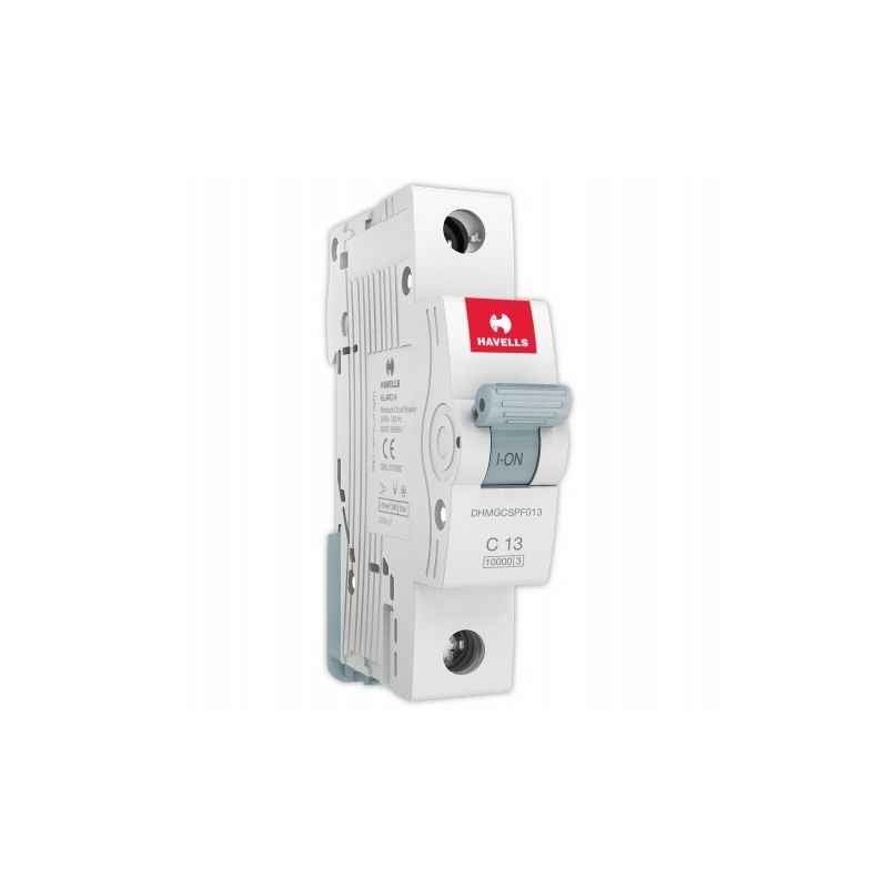
MCB
The MCBs used in this project is shown in Figure 4.17. This cutoff the
electrical supply during any abnormal conditions such as overload or short circuit
to prevent the controller and devices from any kind of fire or electrical hazards.
This works on bi-metal respective principal, so it also protects against solenoid
short circuit current.
3D PRINTED PARTS
The complex and essential parts are 3D printed through an FDM-based 3D
printing machine. An example of 3D printed parts is, the mount for the TTGO
ESP32 LoRa enclosure shown in Figure 4.18 is designed and printed through an
FDM-based 3D printer.
.png)
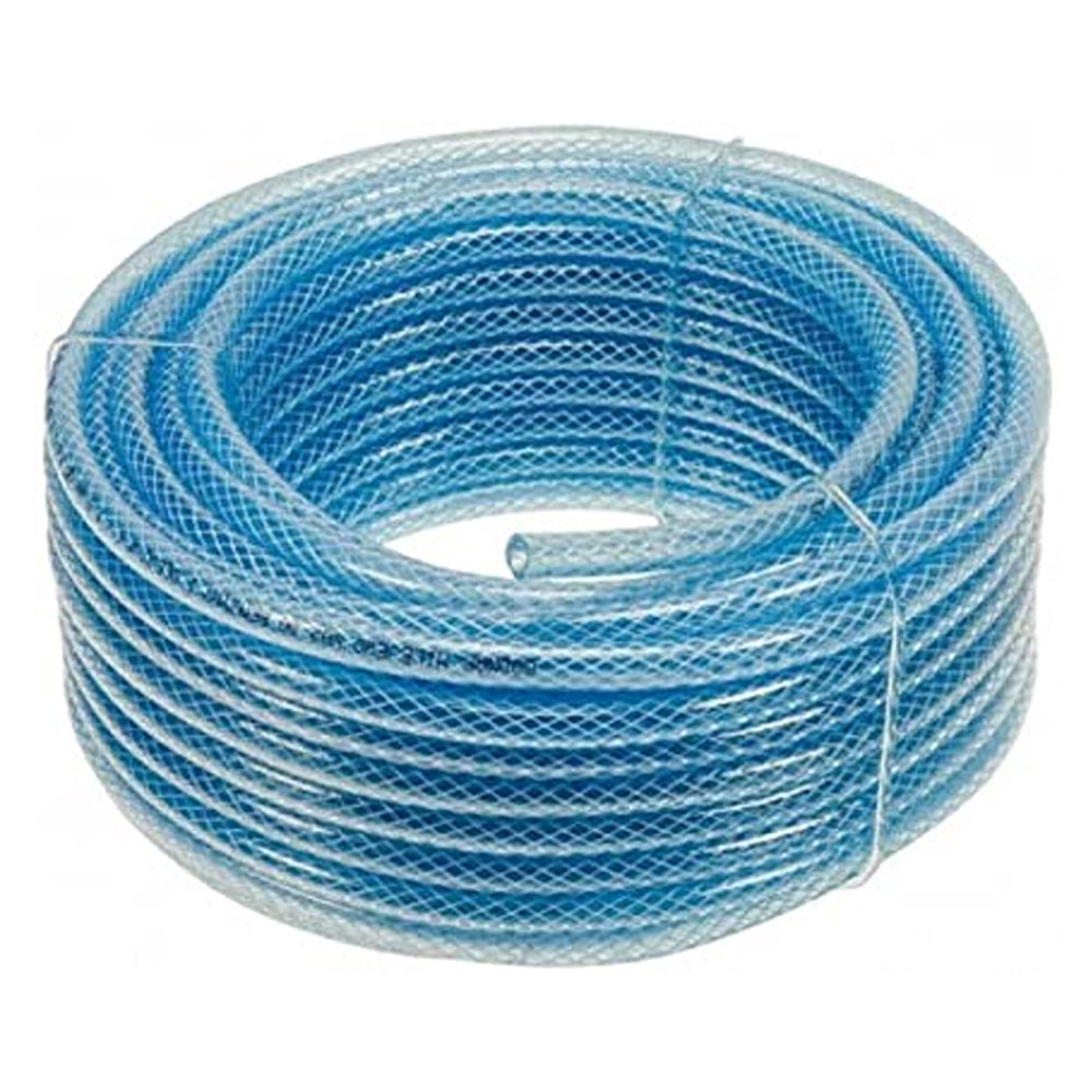
NYLON HOSE
The Nylon hose used is shown in Figure 4.19. They are used for the water
transportation medium in this prototype. Since nylon pipes are less in weight, we
have opted for this instead of metal pipes. The nozzle inlet and the pump outlet
have a diameter of 0.5 inches, so the same diameter of the pipe is used here. The
length of this nylon hose used for the build is 2 m.
BOLT & NUT
The M3, M4, and M5 slotted bolt and nut have been used in this system.
This bolt and nut are used to fix the acrylic and other structures that are used to
build the designed structure. Various sizes of the slotted bolt are shown in Figure
4.20.
.png)
The dimension chart of the different sizes of slotted bolts is shown in table 4.1.
The commonly used bolts in this project are M3, M4, and M5 sizes. The Most
predominant is the usage of the M5 bolt.
.png)
SMPS POWER SUPPLY
The entire power supply for this system is given by SMPS power supply
12V 20A. It rectifies the AC voltage to DC voltage and provides a constant power
supply. It also includes a wired power switch. A power cable is included. Figure
4.21 shows the image of SMPS Power Supply.

KUT TERMINAL BLOCK
A terminal block or terminal connector is a modular block to secures two or
more wires together and it has an insulated frame to prevent a short circuit. A
clamping component and a conducting strip are there to provide conductivity
while connecting the wires through the terminal block. A wire leg is gripped at
the end of the wire that connects with the terminal block. A terminal block image
is shown in Figure 4.23. The terminal block can be easily mounted on the DIN
rail using the mounting arrangements that present on the body of the terminal
block. The usage of terminal block in the control panel for wire connection keeps
the connection ore secure and wires are well organized based on the type. The
part of the terminal block is shown in Figure 4.22.
WIRE DUCT
Wire duct is used for routing and organizing the wiring in the control
panels. Wire duct is cable management used for organizing the wire in the
cabinets and control panels. The size of the wire duct is 25 mm x 25 mm. The
wire duct image is shown in Figure 4.24.

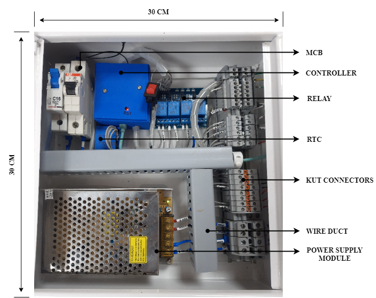
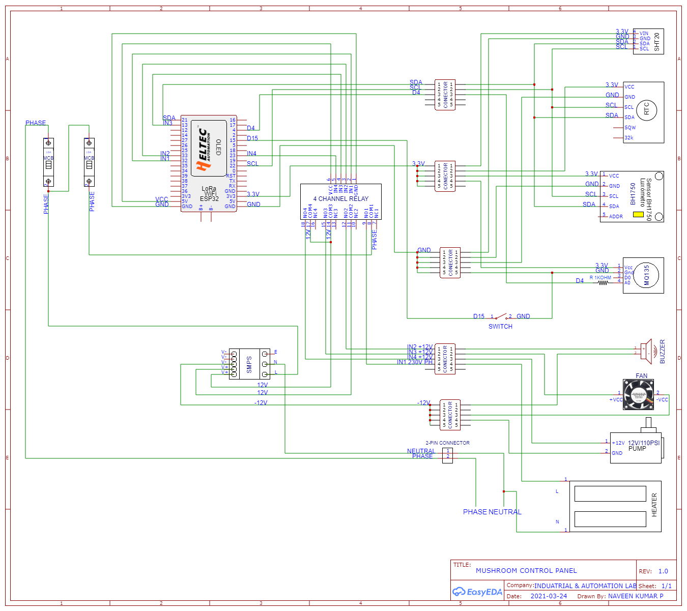
CONTROL PANEL
The control panel is a combination of electrical devices (i.e., MCB,
controller, din rail, wire duct, terminal block) to control the various functions.
The design of the control panel has two categories they are 1) Panel structure, 2)
Electrical Components. The image of the control panel used in this project is
shown in Figure 4.25. The size of the control panel is 30 cm x 30 cm x 10 cm.
The panel structure of the control is the combination of an enclosure and a
back panel. The enclosure of the control panel is the metal box which varies in
size and is made of aluminum or stainless steel. The number of doors in the
control panel depends on the size and application. The enclosure will come with a
UL safety rating.
A back panel is made of a metal sheet mounted inside the control panel to
mount the DIN rail and wire ducts. DIN rail is a mounting structure for mounting
the electrical components and the size of the DIN rail is standardized and made
up of metal.
SOFTWARE REQUIREMENTS:
ARDUINO IDE
The Arduino IDE (Integrated Development Environment) shown in Figure
4.26. It is a multipurpose application that can be used for multiple operating
software like Windows, macOS, Linux, and operating systems which is
programmed in from C and C++. It is helpful to code the required commands and
can be written to any compatible board.
SOLIDWORKS
For the CAD designing of the mechanical structure and analysis of the
system, Solidworks 18.0 has been used which is a licensed version and it is shown
in Figure 4.27.

WORKING PRINCIPLE
SENDER BLOCK DIAGRAM
Figure 5.1 briefly explains the complete flow of this prototype starting
from sensor transmission to the controlling phase it includes the processing
phase also.
.png)
RECEIVER BLOCK DIAGRAM
Figure 5.2 briefly explains the complete flow of the receiver node
which includes data storage, visualization, and analysis.
PIN DIAGRAM
Figure 5.2 briefly explains the complete flow of the network
connections of our prototype
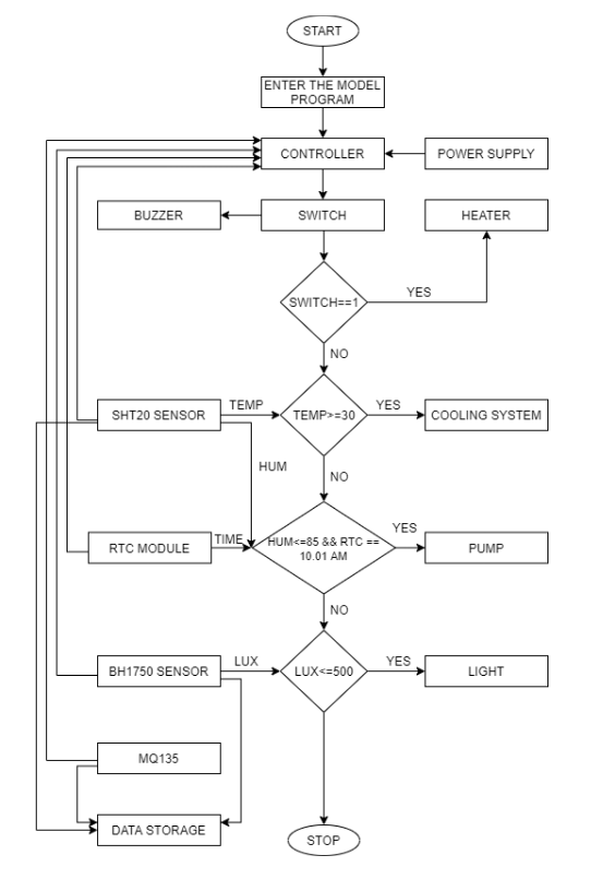
FLOW CHART
Figure 5.4 briefly explains the workflow involved in the development
of the prototype and the mechanisms of the automatic mushroom cultivation
system.

WORKING
The prototype is divided into two phases, they are automatic and manual. In
the manual phase, we are growing the mushroom in a traditional method, that
includes monitoring of temperature required for mushroom cultivation, the
temperature monitored does not a consistent value and it leads to an error so the
growing periods are also more when compared to an automated method.
In the automatic method, the acrylic material has been used for building the
mushroom shed and the required parameters like temperature, humidity, CO2,
and intensity of light are monitored using a dedicated system for controlling. The
data acquired from the temperature and humidity sensor is used to provide
signals to the ventilation system to maintain the optimum environmental
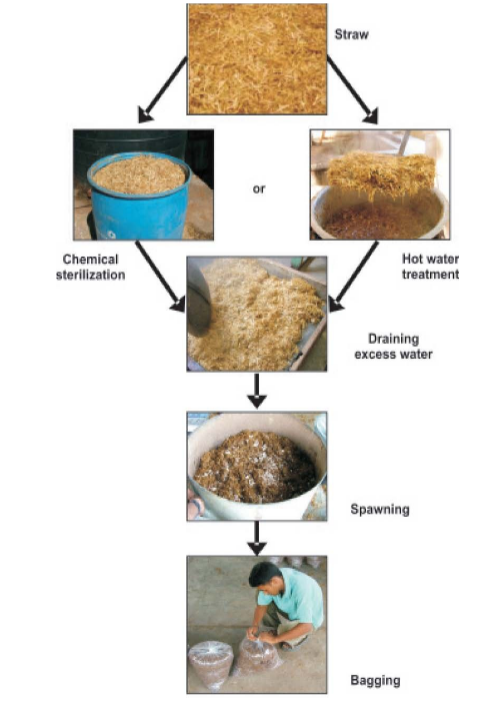
condition required for the mushroom growth [6]. Figure 5.5 represents the
process involved in mushroom cultivation. By using the lux sensor, the intensity
of the light is monitored inside the mushroom shed and it is automatically
changed based on the condition set by the user before understanding the ambient
condition of that particular area.
For the communication purpose, the low power wide area network
technology has been used, using this method the data can be transmitted from a
non-connected area to a network bound area as its range is about 10 km, it would
be really useful to fix this connection in the field and process those data in a
separate connected environment for the fast decision making and controlling.
The automatic mushroom cultivation is explained in the steps given below.
Step 1: The hay or straw required for building a base of a mushroom bed is
developed.
Step 2: The optimum temperature, humidity, the light intensity required for
the growth is about 25oC - 30oC, 85%RH, and 500 – 2000 lux (during
29
daytime) [6]. It is monitored using a TTGO LoRa32 controller.
Step 3: The required parameters are monitored and data is stored for the
further interpretation process.
Step 4: The required parameters are monitored at different growing stages
and data stored is then pushed to the cloud.
Step 5: A separate web and mobile application are developed for monitoring
the data stored in the cloud and those data are analyzed and used for building
a prediction model for the yield and sales forecasting.
DEVELOPMENT PHASES
The development of these prototypes undergoes four stages they are
design, bed preparation, controlling, and visualization stages.
DESIGN PHASE:
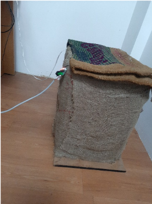
TRADITIONAL SHED DESIGN
The wooden reaper has been used to make the outer structure of the shed
and coconut fronds are used for the upper covering of the shed, the entire
mushroom shed is covered using a jute bag to maintain the temperature and
relative humidity. Figure 5.6 shows the shed developed for the traditional way of
mushroom cultivation.
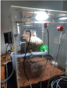
AUTOMATIC SHED DESIGN
The enclosure of the sensor is completely made of Acrylonitrile Butadiene
Styrene (ABS) it is a common thermoplastic polymer its glass transition
temperature is approximately 105 ̊ C. ABS is amorphous and therefore has no
true melting point, it is insoluble in water. The ABS material is FDA cleared,
recyclable and eco–friendly. It holds pressure up to 450 PSI. We choose this
because it has a low production cost. The conceptual design was made using
solid – works designing software and the model is made using Rapid prototyping
in the form of injection modeling technique [6]. Figure 5.7 shows the structure
developed for the automatic way of mushroom cultivation.
The automatic mushroom shed is build using acrylic material and the base
is fully composed of red soil and the same material is used to cover the upper
part. The sensors are fixed in the shed using the 3D printed cases in the required
position to monitor the required parameters. To maintain the temperature inside
the shed a closed-looped cooling system is fixed in the shed and to maintain the
humidity an automatic sprinkler system is fixed.
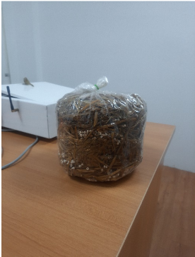
BED PREPARATION PHASE
The hay required for the bed preparation is first sterilized at a high
temperature for two hours and dried for two to three hours in ordered to remove
the moisture present in the hay. The base of the polyethene bag which is already
sealed is again tightened using a rope in ordered to prevent the airflow inside the
bed. Now the seeds required for the growth are placed in the polyethene bag with
a base made of hay and the same is made for three layers. The layer is then
33
compressed to make it air-tight and hanged in a vertical position and holes are
made random throughout the bed for the required growth of the mycelium. The
Figure 5.9 represents the mushroom bed prepared for this is system.
CONTROLLING PHASE
At the initial stage, the hay is heated to get sterilized, which is required for
bed preparation. The time from the RTC module is taken as feedback to the
controller and the heating of hay is controlled using the acquired signal.
In this prototype we are monitoring few parameters such as temperature,
humidity, CO2, and light intensity, we are controlling the temperature inside the
shed using a cooling system, humidity using a sprinkler system, and intensity of
light using the lighting system.
When the temperature is in a range between 25 - 30oC the controller
functions normally, but if the temperature is measured below 25oC the heating
system is switched on, and also if the temperature exceeds 30oC the cooling
system is on until a temperature is being monitored below the optimum level.
34
When the humidity inside the shed is in the range between 85 – 90%RH the
controller does not require any action to perform, but if it is measured below
85%RH or above 90%RH the sprinkler system gets activated based on the
feedback from the controller. Also, the RTC module is used to send feedback to
the controller, and based on the condition provided by the user the water gets
sprinkled after daily monitoring at 10.00 AM, and based on the humidity level the
function gets executed. The light intensity is monitored 400 – 2000 lux during the
daytime and if the value gets changed then the intensity gets automatically
adjusted based on the feedback from the controller.
The LoRa technology has been used for communication purpose which
there are two parts, the first part is the sender in which all the input devices and
output devices are connected to the controller and this place lacks the network
bandwidth for the transfer of data so the second part called receiver part which
receives the values pushed by the controller using LoRa technology and this part is
built with the network infrastructure, from this location the data is pushed to the
cloud. The user could also view the data from the controller without the internet
connection using an OLED display. The sender is fixed in the control panel which
is located near the mushroom farm and the receiver is placed based on the user’s
convents the data gets transmitted between them within a range of about 10 km.