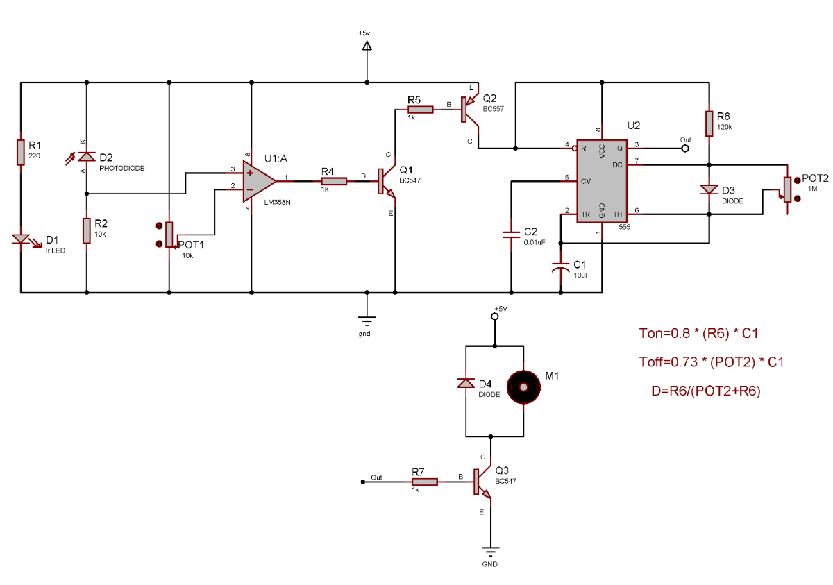
Step1:
Connect 220ohm resistor (R1) to +5v & the Ir Led (D1) positive terminal, negative terminal to ground(GND).

Step2:
Next, Connect the negative terminal of photo-diode (D2) to +5v & 10k ohms resistor(R2) to positive of photo-diode and GND.
Step3:
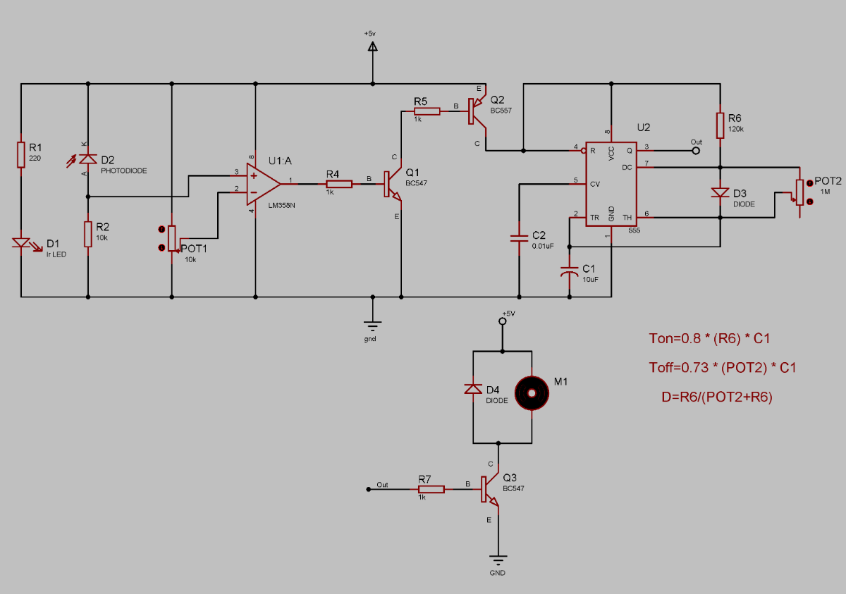
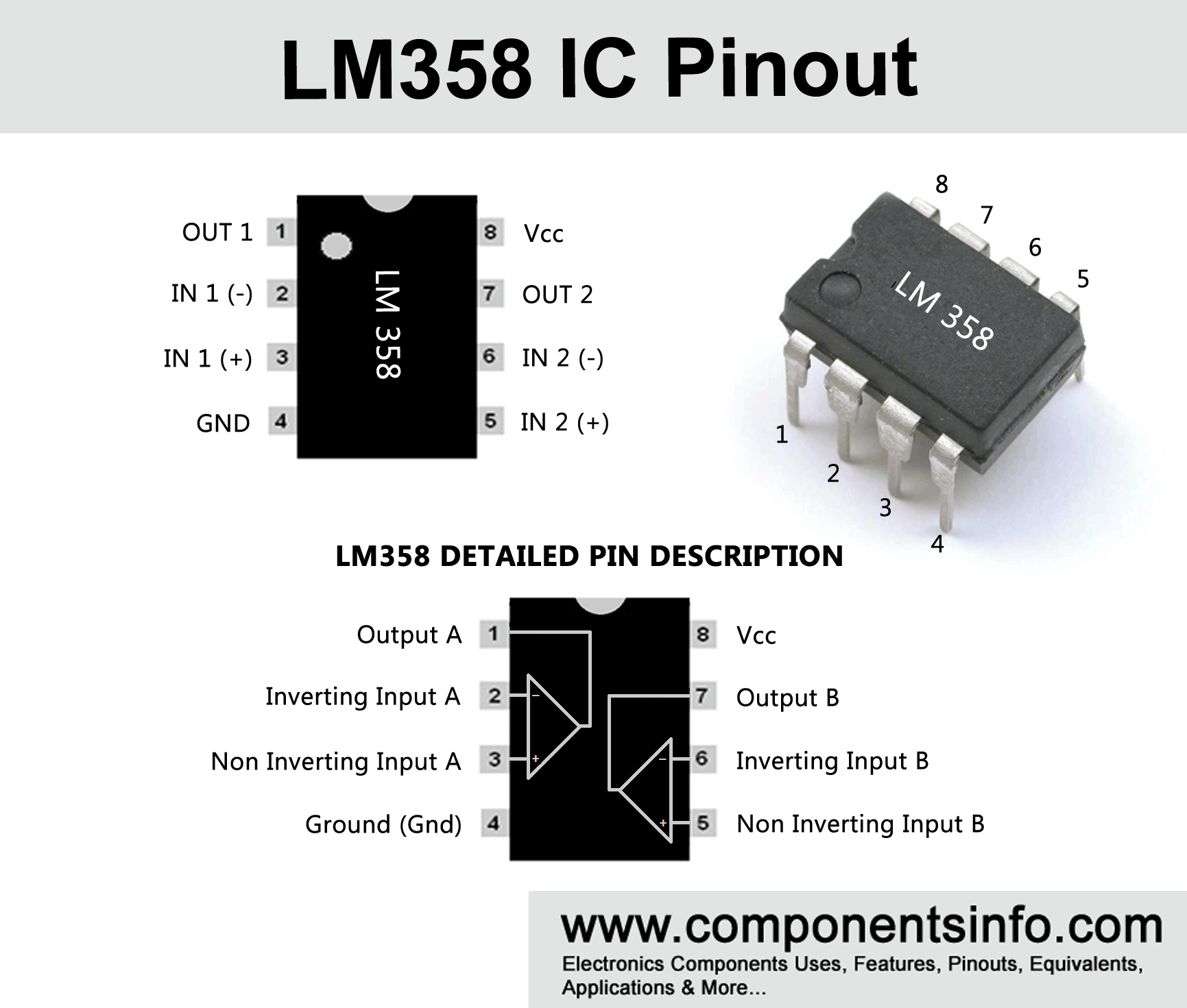
Connect LM358 ic (U1) pin 8 to +5v & pin 4 to GND. Connect a wire to the positive terminal of photo-diode to the non-inverting terminal of the op-amp pin 3
Step 4:
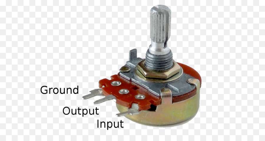
Potentiometer (POT1), connect end terminals to +5v and GND. The remaining terminal is connected to pin 2 of the op-amp which is inverting terminal. This potentiometer uses a set point or reference voltage to the op-amp.
Note: The output will high if the non-inverting terminal is more than the inverting terminal voltage which is set by us in step 4
Step 5:
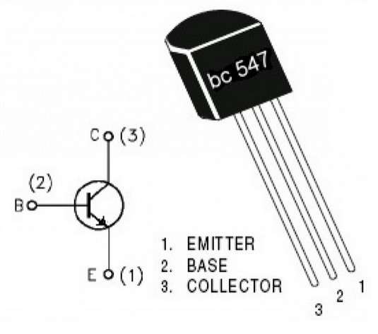
The output pin 1 of the op-amp connected to the resistor 1k ohm (R4) and another end of the resistor to the base of transistor BC547 (Q1)
Step 6:
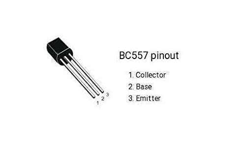
The Transistor BC547 (Q1) emitter connected to GND. The collector of the transistor BC547(Q1) to 1k ohm resistor(R5) to the base of the transistor BC557 (Q2)
Step 7:
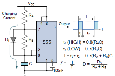
The emitter of BC557 (Q2) connected to +5v and collector to pin 8 & pin 4 of 555 timer IC (U2).
Step 8:
Connect 10uF capacitor (C1) positive terminal to pin 2 & pin 6, the negative terminal of the capacitor to ground.
Step 9:
Connect 10nF capacitor (C2) positive terminal to pin 5 & the negative terminal of the capacitor to ground.
Step 10:
Connect diode (D3) cathode terminal to pin 7 & anode terminal pin 6, Potentiometer (POT2) connect one end terminal to pin 7 & middle terminal to pin 6.
Note: The Turn off time can change by turning the potentiometer (pot2).
Step 11:
Connect Resistor 120k ohm (R6) to pin 8 & pin 7
Note: Turn on time can change by changing the Resistor (R6) value.
Step 12:
The output pin 3 of IC (U2) connected through to Resistor (R7) to BC547 (Q3) base.
Step 13:
The transistor (Q3) collector connected to the motor with a free-wheeling diode(D4) to +5v.The Emitter to GND.
