HEADLIGHT DIMMER

Principle of this prototype
The basic principle of operation is can be done where we have to correctly assemble the components as per the block diagram. The LDR is a variable resistant when it is connected to the resistors it acts as a voltage divider. For that, the transistor BC547 is used to balance the network. Which is also connected to the Relay circuit. In Arduino, the program is coded using embedded C to control the switching of the light. And the other two LEDs are connected to the other end of the relay circuit. Each LED represents the high and low beam which is used for indication purposes for example red and green. Whether the headlight is in high beam the red LED will glow for low beam green LED will glow. The comparator is the basic operation with the transistor and the LED bulbs. When the high-intensity beam falls on the LDR there will be a potential drop and that triggers the transistor. The transistors work on conduction mode to switch the relay. When there is no approaching vehicle the transistor will not trigger.
Working of the circuit
Based on the principle the actual working model is constructed. The same components are used as mentioned earlier in the principle. For current source purposes, we have used a 12V adapter here. But in real-time power can be taken from the car battery. The Arduino coding is used to control the switching of the headlight.
Case 1:
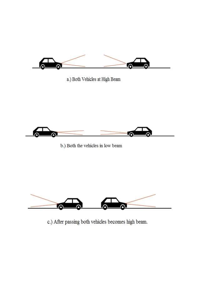
When our vehicle is approaching other vehicles with high intensity. Then the high intensity is sensed by the LDR sensor which makes the circuit potentially unstable. That will trigger the transistor BC547 which is connected to the relay circuit. Due to the triggering of the transistor, the green bulb will glow and thus indicates that our headlight switches from high to low.
Case 2:
When there is no approaching car then there will be a potentially balanced circuit network. Triggering will not take place therefore the green led switches to red indicates that the headlight is turned low to high beam.