

1.Introduction:
Obstacle detection robots detect the obstacle to stop themselves. This technique can be used in a vehicle in reverse gear to detect the obstacle and stop a vehicle. Also can be used in big industries where robots are used to shift the heavy jobs, these robots detect an obstacle in their predefined path and stop itself.
2.Arduino Uno:
Arduino platform offers open-source hardware and software that is easy to use and is used widely for projects.
- Pin no 7,8,9,10 are used to driving the motors.
- Pin no 11 used to enable the motor driver IC.
- Pin no 12 is used to get interrupt from the IR module.
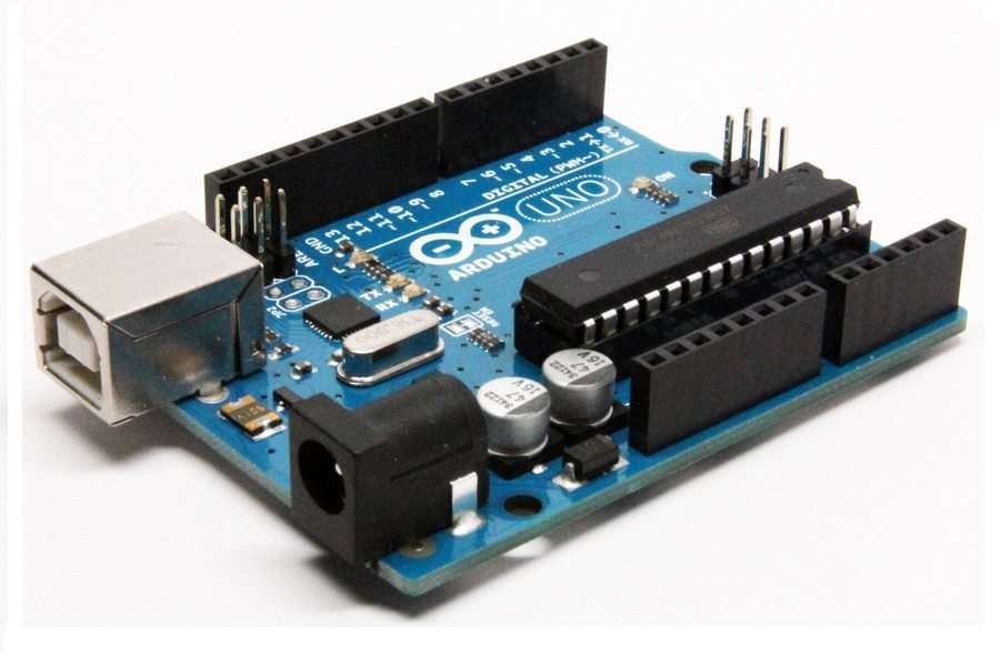
Fig1.Arduino
3.Motor driver:
- This module can drive two DC motors.
- If we give 1,0 to driver motor rotates in the forward direction, for input 0,1 motor rotates reverse direction, for 0,0 and 1,1 motor stops rotating.
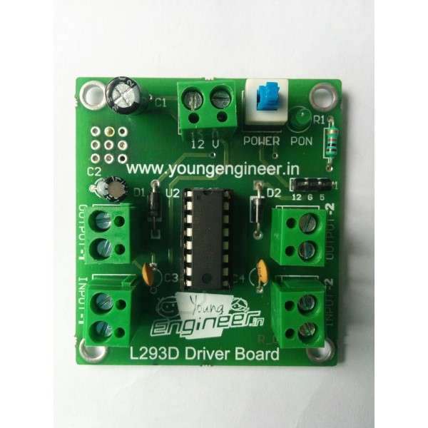
Fig2.Motor driver module
4.IR Sensor Module:
- It sends IR rays continuously when obstacle detected it capture reflected waves from the obstacle.
- When obstacle detected it sends ‘0’ on the output pin.
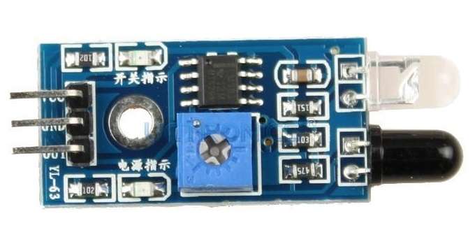
Fig3.IR Module
5.Circuit Diagram:
- Pin no 7,8,9,10 are the interface with the L293D motor driver module to drive the motors.
- Pin no 12 interfaces with an IR module to get interrupt from it.

Fig4.Circuit Diagram
7.Program
int obs=1;
void setup() {
 /*Declare input output pins */
 pinMode(7,OUTPUT);
 pinMode(8,OUTPUT);
 pinMode(9,OUTPUT);
 pinMode(10,OUTPUT);
 pinMode(11,OUTPUT);
 pinMode(12,INPUT);

}

void loop()
{
 obs=digitalRead(12);
 if(obs==1)
 {
   /*Move robot forward*/
 digitalWrite(7,HIGH);
 digitalWrite(8,LOW);
digitalWrite(11,HIGH);
digitalWrite(9,HIGH);
 digitalWrite(10,LOW);
}
else
{
 /*stop robot*/
 digitalWrite(7,LOW);
 digitalWrite(8,LOW);
digitalWrite(11,LOW);
digitalWrite(9,LOW);
 digitalWrite(10,LOW);
}
}