A tachometer is an instrument measuring the rotation speed of a shaft or disk, as in a motor or other machine. The device usually displays the revolutions per minute (RPM) on Analogue dial, or on digital display. In this project, tachometer is made using an IR Sensor module as unit for measuring the number of rotations.
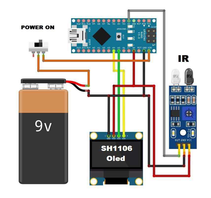
Simply we have interfaced the IR sensor module with Arduino nano and the SH1106 Oled display. The sensor module consists of IR Transmitter & Receiver in a single pair that can work as a Digital Tachometer for speed measurement of any rotating object.
One diode transmits IR rays which reflect back to the receiver diode and then IR Module generates an output or pulse which is detected by the Arduino controller.
Arduino calculates RPM for a minute using the given formula:
rpm = (objects / 3.0)*60;
because in our case we have 3 obstacles (objects) in one full circle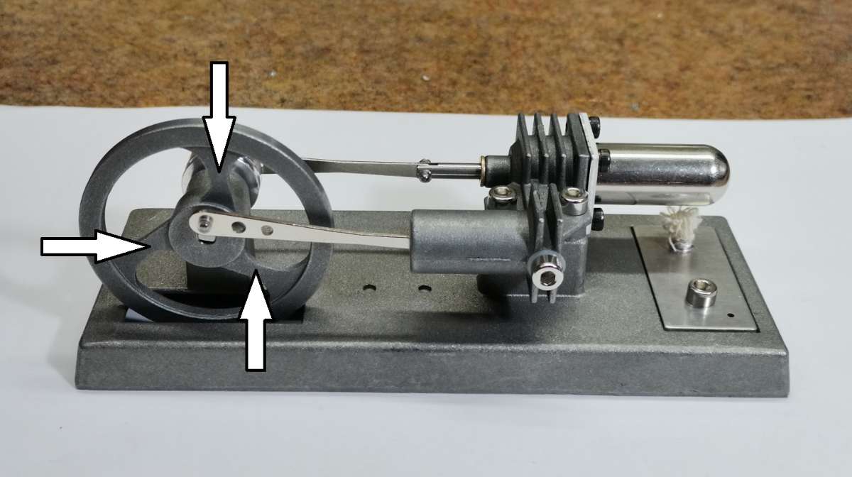
The device is very simple to build and consists of several components:
- Arduino Nano microcontroller
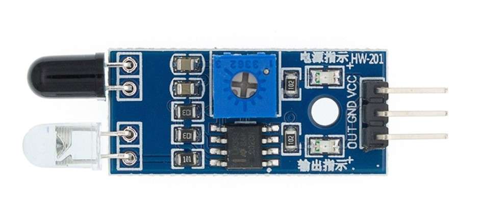
- IR sensor module
- and SH1106(or SSD1306) Oled display
If you want to make a PCB for this project, or for any other electronic project, PCBway (www.pcbway.com) is a great choice for you. PCBway is one of the most experienced PCB manufacturing company in China in field of PCB prototype and fabrication. They provide completed PCB assembly service with worldwide free shipping , and ISO9001 quality control system. Also, on their site there is an online gerber viewer where you can upload your gerber and drill files to render your board.
Let me mention that instead of SH1106, an SSD1306 OLED display can be used, so in the code everywhere you simply need to replace SH1106 with SSD1306.
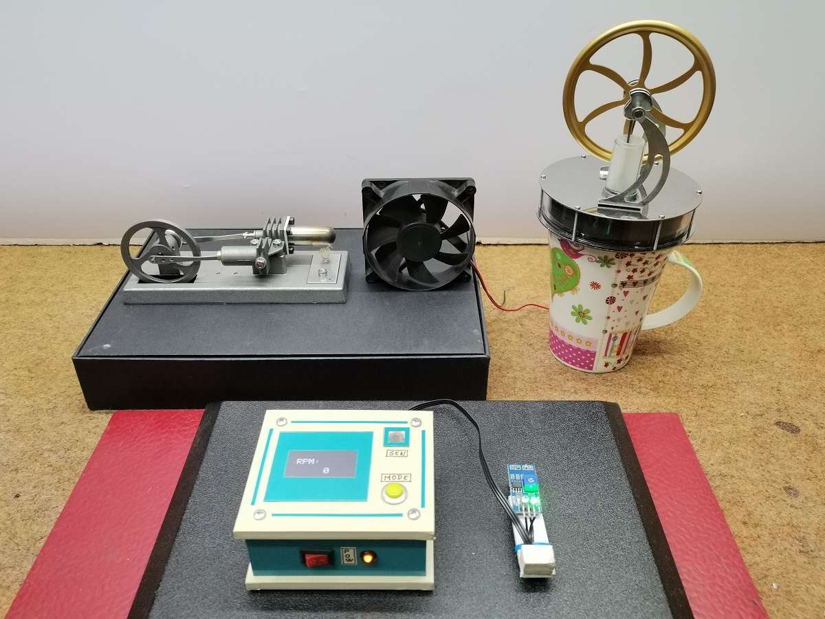
When measuring, we need to place the sensor at a certain distance from the rotating object, and this distance can be defined by the trimmer potentiometer on the IR module. In this case, I will measure the RPM of two small Stirling engines, as well as one PC power supply fan.
By the way, in the description of the construction of the device, there are also brief instructions for assembling the high-temperature Stirling engine.
Immediately after starting the device, my logo appears on the screen, and after a few seconds the measurement can begin. It is useful to know that any image can be converted into a C code array using special programs for this purpose, and even online.
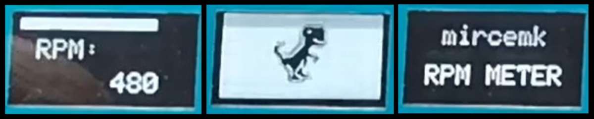
For greater visibility, a progress bar proportional to the number of revolutions appears on the upper part of the screen . Depending on the range of values for which we will use the tachometer, in a part of the code:
display.fillRect(0,4, map(rpm, 0, 1000, 0, 128), 8,WHITE);
another value can also be mapped.
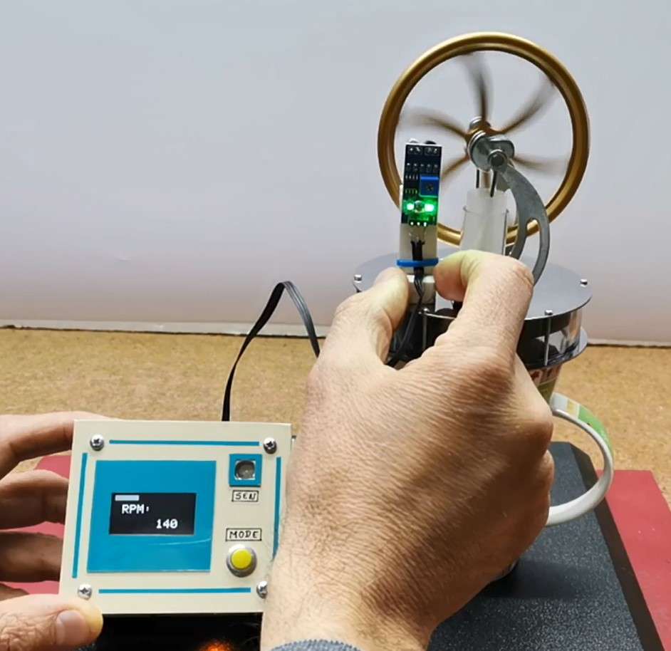
First, we measure the rotational speed of a low temperature Stirling engine. This machine has 6 obstacles so we adjust the arduino code accordingly
rpm = (objects / 6.0)*60;
For this machine to work, the cup must be filled with boiling water.
Next, we measure the rotational speed of a high-temperature Stirling engine.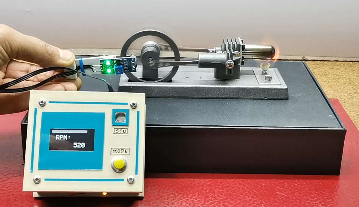
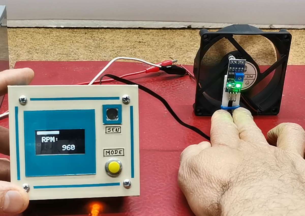
And finally, we measure the rotation speed of the PC fan.
The device is built into a suitable box made of 5 mm PVC board, covered with self-adhesive colored wallpaper. In fact, I used the box from one of my previous projects, so the light sensor and the button have no function in this specific project.