
The sun provides more than enough energy to meet the whole world’s energy needs, and unlike fossil fuels, it won’t run out anytime soon. Solar power cell is are renewable CO2-free power source that convert Sunlight into Direct Current (DC) electricity. Solar irradiation is the power per unit area received from the Sun in the form of electromagnetic radiation, and is typically expressed in watts per square meter (W/m²). This data is used to determine the potential for solar power generation, and it helps in designing and optimizing solar panels and other solar energy systems.
The simplest way to measure solar radiation is to connect a low value resistor in parallel with the solar cell and measure the voltage drop across the resistor.
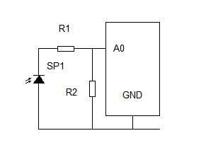
The current flow is roughly proportional to the illumination intensity. However, this method is not precise enough, and fortunately for a very low price we can find a current sensor board with excellent features.
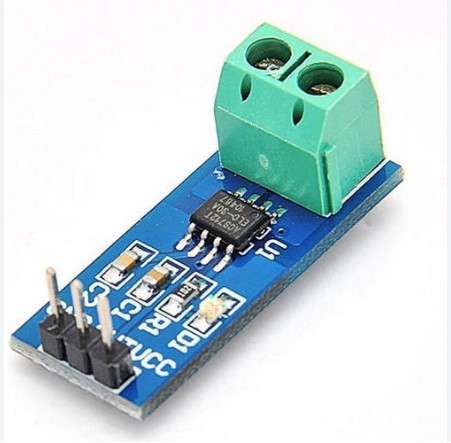
The current sensor module utilizing hall-effect principle which voltage is produced from the movement of current within the region of magnetic field. The voltage produced by hall effect is directly proportional to the applied current making it suitable to estimate the applied current from the voltage sensed.
This project was originally presented on the Solarduino site and all credit goes to them. On the site you can also find detailed instructions as well as links where you can get all the components. I made minor adjustments to the code based on the components I had at the time of building the device. Instead of a 16x2 LCD Display Shield I use a standard 16x2 LCD Display with a separate Initialization Button.
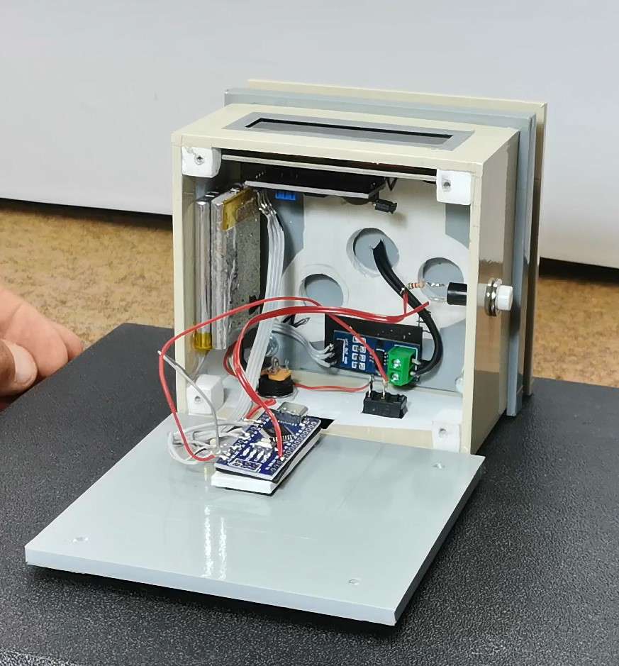
The device is extremely simple to make and consists of only a few components:
- Arduino Nano microcontroller board
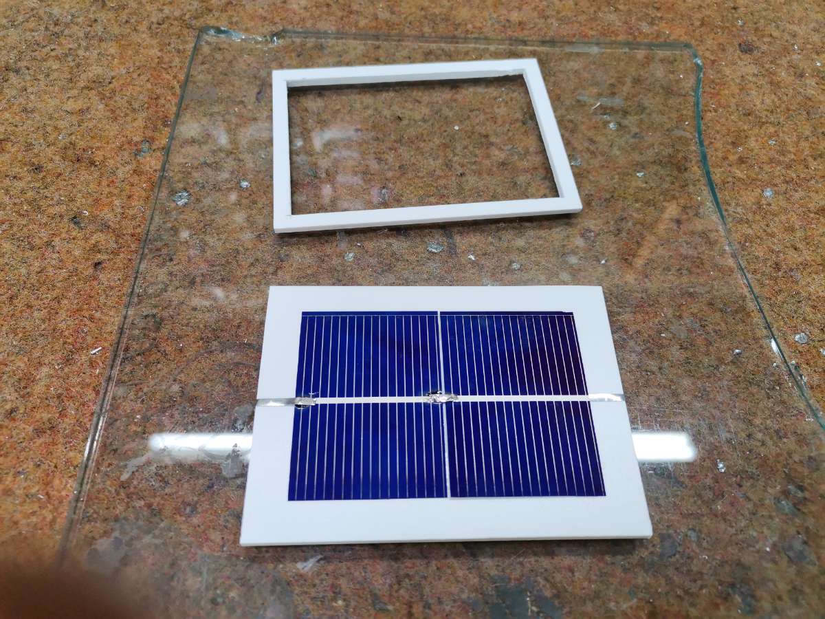
- Solar Cell (preferably with a voltage of 0.5V and a short-circuit current of 0.5 to 1 A) - If we do not have information about this value from the manufacturer, we can determine it with the following procedure: We connect the solar cell directly to the ammeter, and point it in the direction of the sun so that the light falls on it at an angle of 90 degrees. The current that is read at this moment is called Short circuit current. Then this value is entered into the code.
- ACS712 Current Sensor Module rated at 5A
- 16x2 LCD Display with I2C communication protocol
- Button
- and two resistors
The sensor is connected to the solar cell with relatively thick and short wires to avoid interference and losses. The voltage output of the board is connected to the power supply and the A1 analog input of the Arduino.
Now let's consider the way of working with the device as well as its functioning in real conditions.
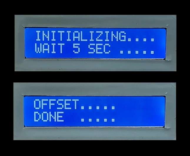
Immediately after turning on the device, we need to cover the sensor and press the button, and after that, initialization and calibration of the sensor takes place, which lasts about 5 seconds, then the message "OFFSET DONE" appears briefly, so next we direct the cell towards the sun. Now, I will use this Lamp instead of Sun.
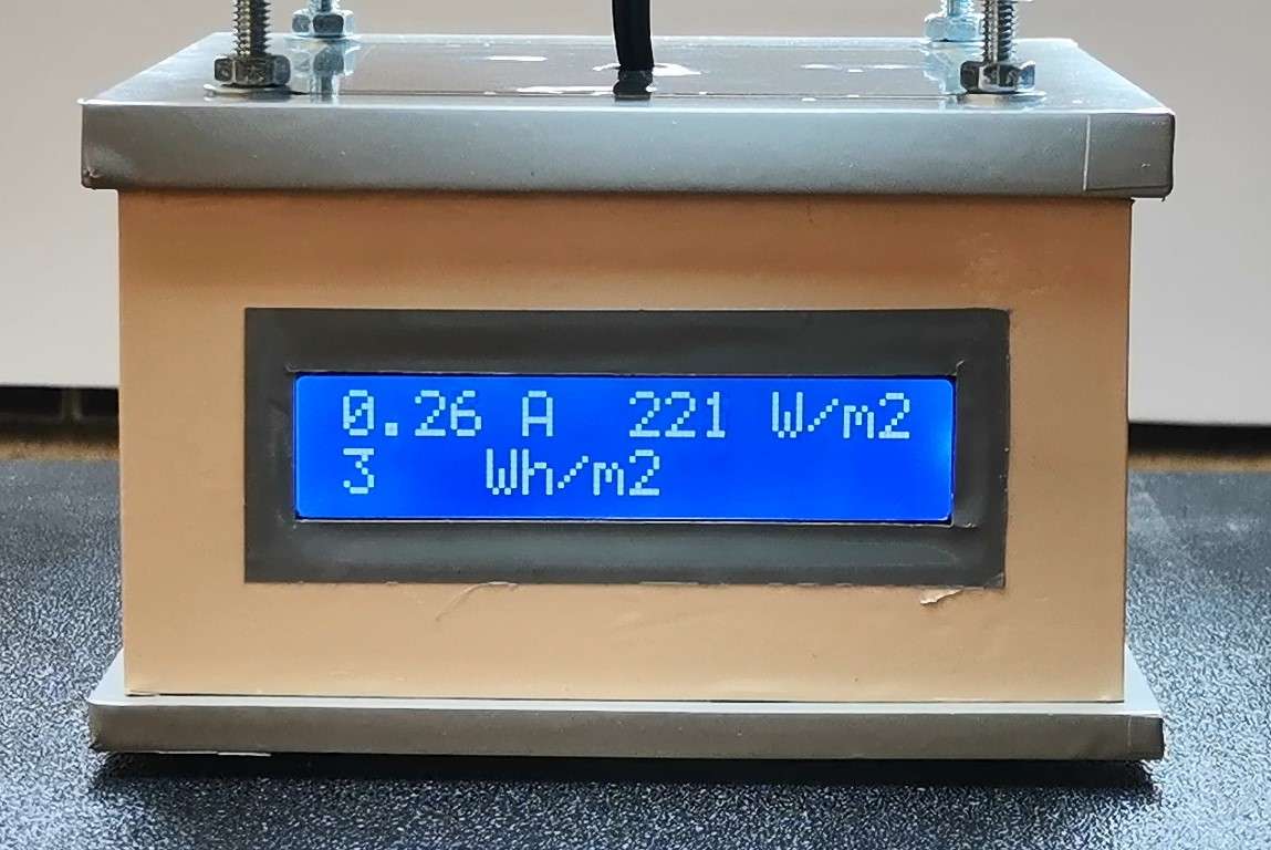
After that, the data obtained from the measurement is displayed:
- The first row shows the amount of current generated by the panel, and the current power delivered by a panel with an area of 1 square meter.
- The second row shows us how many Watt-hours are generated from the beginning, until the moment of reading.
In this way, knowing the number of sunny days during the year for a selected location, we can relatively accurately calculate how much electricity would be produced annually with a given area of solar panels. Now let's see how this would look outside in real sunlight exposure. As we can see, the energy generated depends significantly on the angle at which the sunlight is received. General rules for the physical placement of solar panels are that the vertical angle of the panels should be approximately the same as the Longitude of the given location, and the orientation should be South, but not magnetic South that the compass shows, but true South with calculated magnetic declination.
And finally a short conclusion.
This is a very cheap and simple to make, but extremely useful instrument, especially when designing such systems to simulate and provide feasibility study of a location or site whether it is viable to install Solar PhotoVoltage System