Self-balancing devices are electronic devices that use sensors and motors to keep themselves balanced while in use. They uses gyroscopic sensors and accelerometers to detect the movement of the balanced object and adjust the speed and direction of the wheels accordingly, allowing to control the device through shifts in their weight.
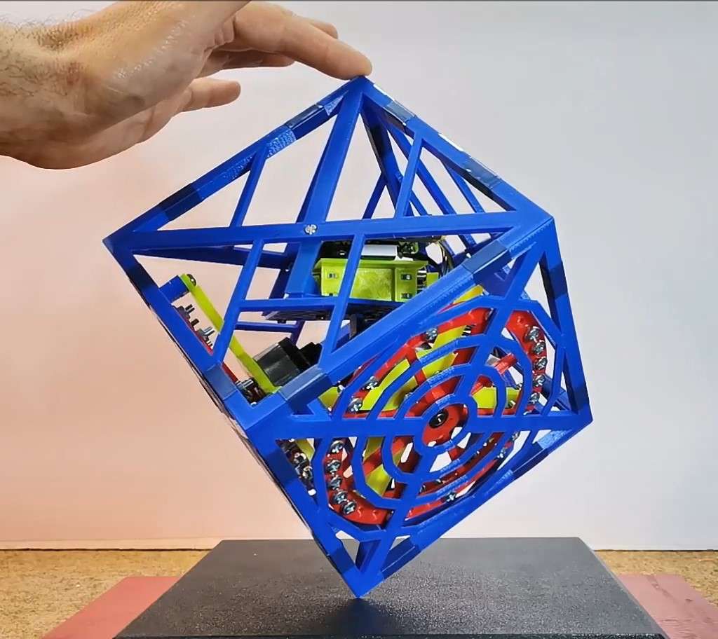
This time I will present you a project in which the balanced object is a 3D printed plastic cube, inside which the reaction wheels and control electronics are located.
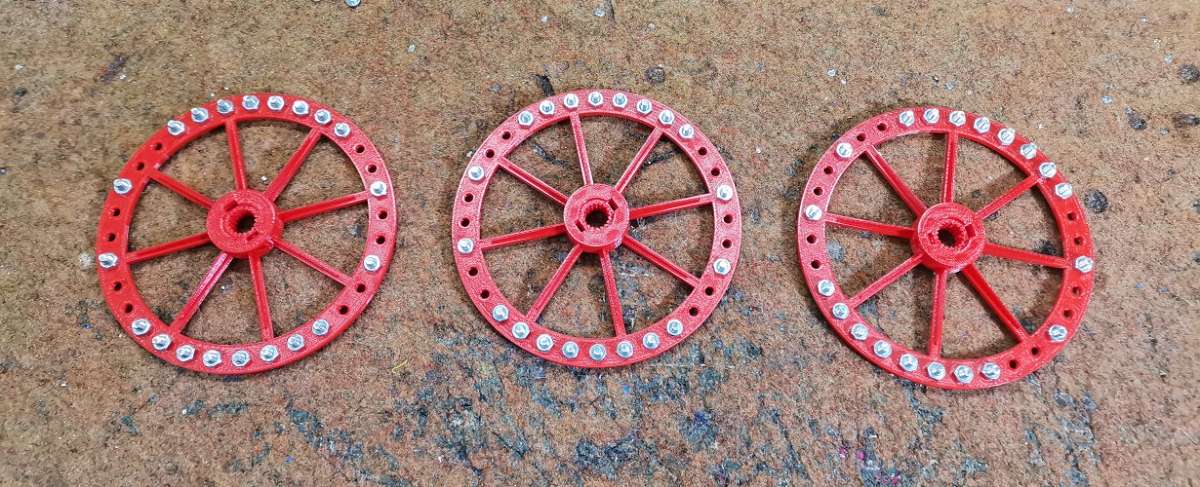
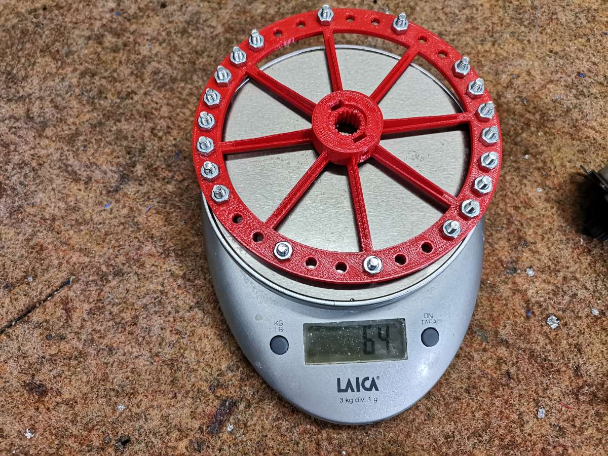
Nuts and bolts are added to the wheel in order to increase its weight, thus increasing the impact of the rotation on the whole device.
Otherwise, this is an open source project and the original code and .STL parts for 3D printing can be downloaded from ReM-RC GitHub. After a long search for such similar projects on the Internet, I can confidently say that this is the best-made project in this area in every way, such as simplicity, easy setup, and stable operation.
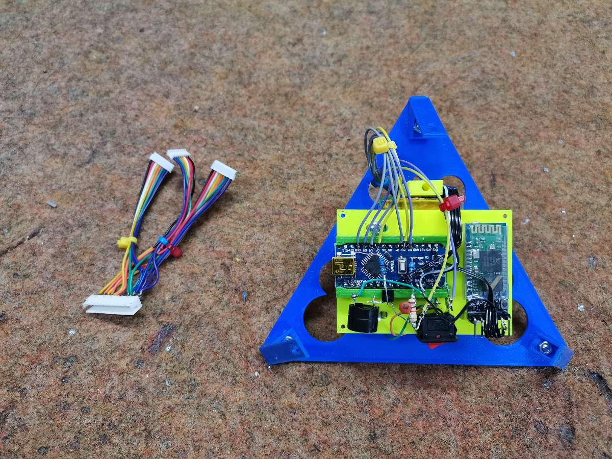
The control part of the device consists of several components:
- Arduino Nano microcontroler board
- MPU6050 Gyroscope and Accelerometer module
- NPN Transistor
- Buzzer
- three resistors
- Battery
- and optionally Bluetooth module for easier tuning
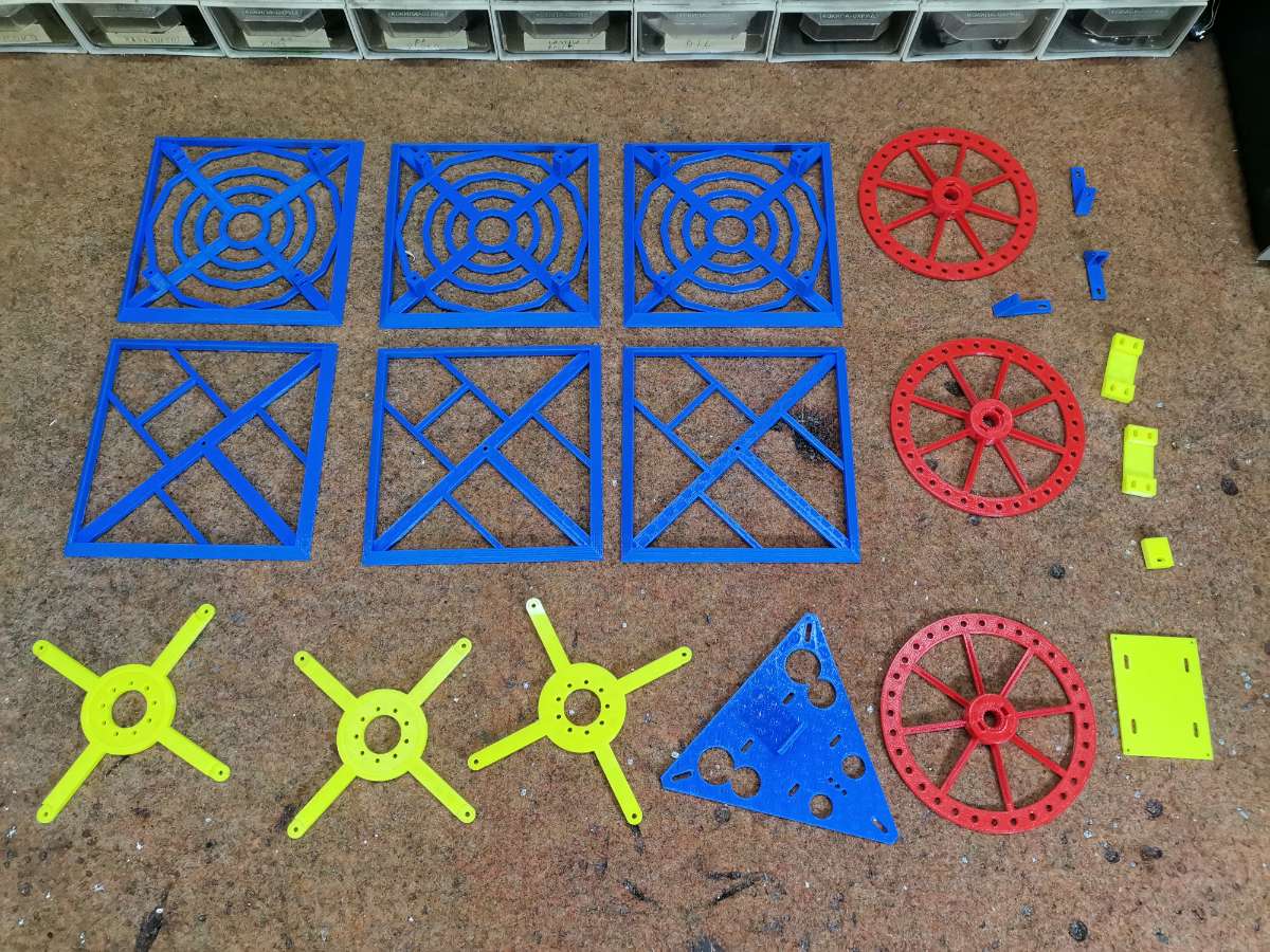
3D printed part consist also several components. Each large part takes more than 2-3 hours to print, so it took me a few days to print all the parts.
- reaction wheel sides and we need three such part
- other three sides of the cube
- reaction wheels that serve to balance the cube
- mount plate for the batteries and the controller, on which there is a mounting surface for the mpu6050 sensor board.
- Battery holders
- and controller mount plate, and mount plate holders
Otherwise, an ESP32 microcontroller can be used instead of an Arduino, and in that case Bluetooth is built into the microcontroller.
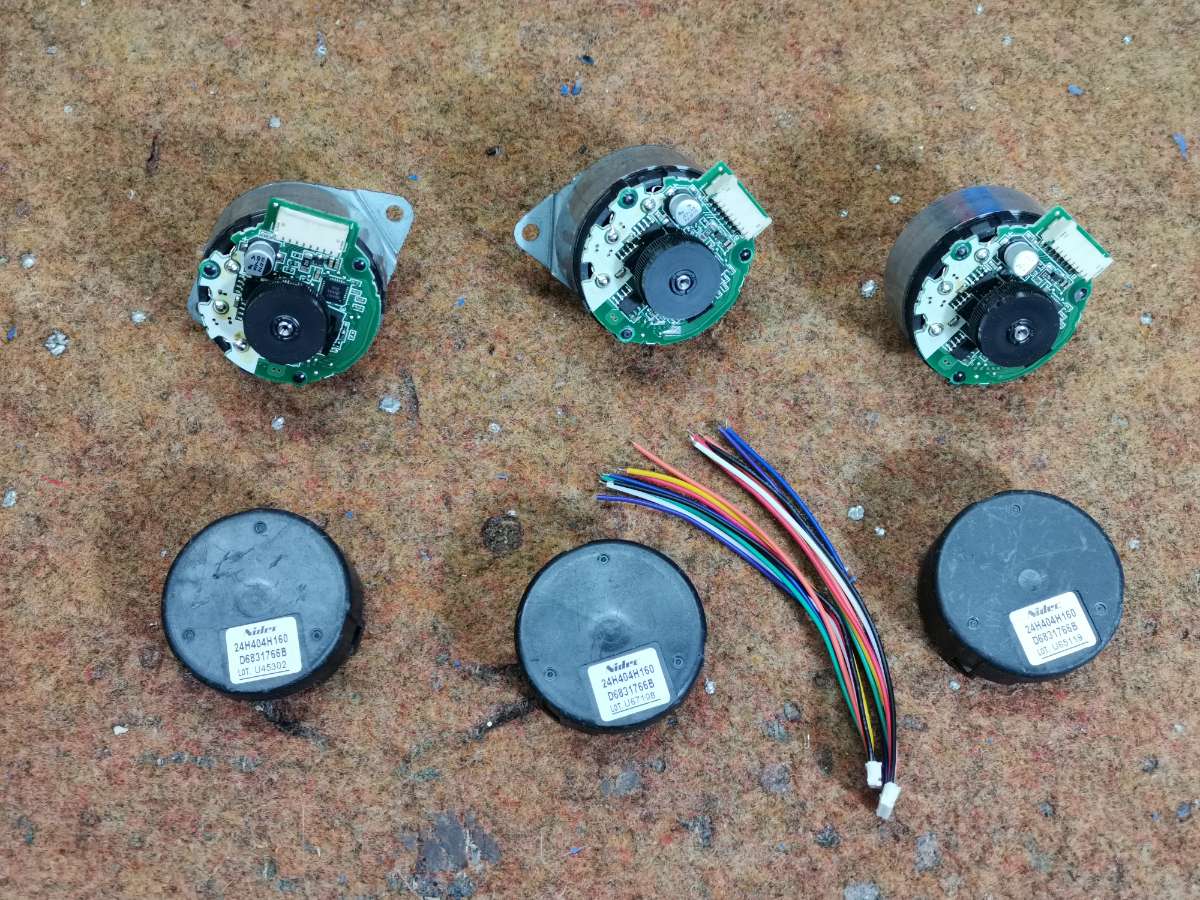
The three motors are "Nidec 24H" type:
First let's see how the device works in real conditions. Before putting it into operation, it should be calibrated. Setting procedure is very simple. Setting procedure is very simple. First connect to controller over bluetooth. You will see a message that you need to calibrate the balancing points. Send c+ from serial monitor. This activates the calibrating procedure. Set the cube to one of the balancing points (edge or vertex). Hold still when the cube does not fall to either side. Send c- from serial monitor. This will write the offsets to the EEPROM.