VU meter or volume unit meter is a device intended for visual presentation of the audio signal. It typically consists of a series of LEDs arranged in horizontal bar graph configuration, wictch light up proportionally to the level of the audio signal they receive. In some of my previous videos , I present more different types of such devices.
This time I will present you a way to make an advanced VU meter witch for indication uses a 5050 type LED strip with a built-in WS2812B chips and the parameters of each diode can be controlled individually.
Thanks to this feature of the led strip, with a minimum number of components and relatively complex code, can be made a VU meter with many functions and visual modes. The project was originally developed by "ericBcreator" and then it was repeatedly made and modified by many self-builders.
The device is relatively simple to make and contains only a few components:
- Arduino nano microcontroller board
- 10K resistors 5 pieces
- 2 Potentiometers 10K
- 2 Buttons
- switch
- Audio Input Jacks
- and VS2812B LED strip with 72 LEDs

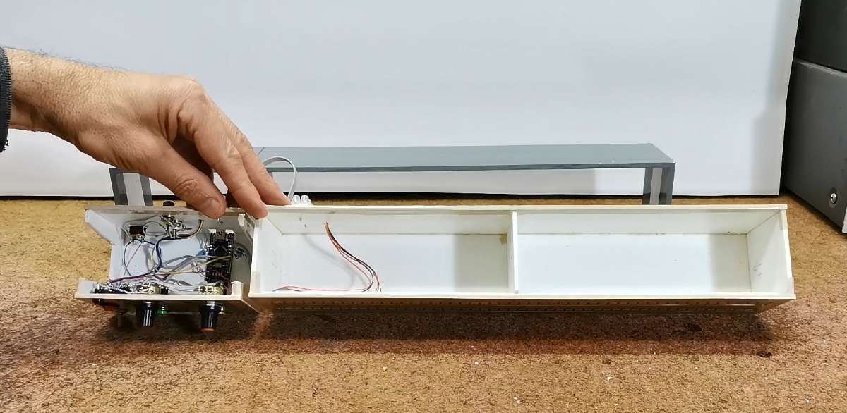
As you can see, the control part and led strips are placed in separate boxes, in order to have a better visibility during the presentation of this device. Otherwise, my original idea is that the control part will be built into the box with the led strips, and the potentiometers and buttons will be on the back of the box, and the width of the box would be standard 19 inches to fit as part of the whole audio system. Based on this dimension, the number of LEDs in the strip would be adjusted.
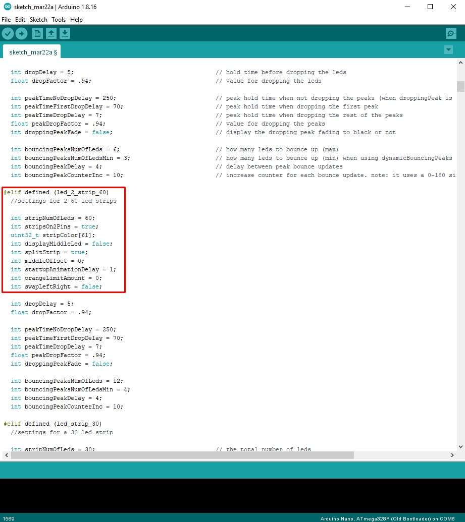
The code is highly customizable and all important settings are commented out. So we can easily adjust it according to our current conditions.
Speaking of the number of diodes in the strip, several values are predefined in the code. If the project requires us to have a different number of diodes than those predefined in the code, as in my case, where I have 50 diodes per channel, then we simply cut the strip to the required number, and in the code we uncomment the line where more diodes are defined.

And now let me explain all the settings and options, as well as see how this device works in real conditions:
- One potentiometer regulates the sensitivity of the input signal
- the other potentiometer serves to regulate the light intensity of the LEDs
- switch for peak hold function
- a button that can be used to select one of 12 different color schemes
- and the other button will cycle through spinning and/or pulsing modes.
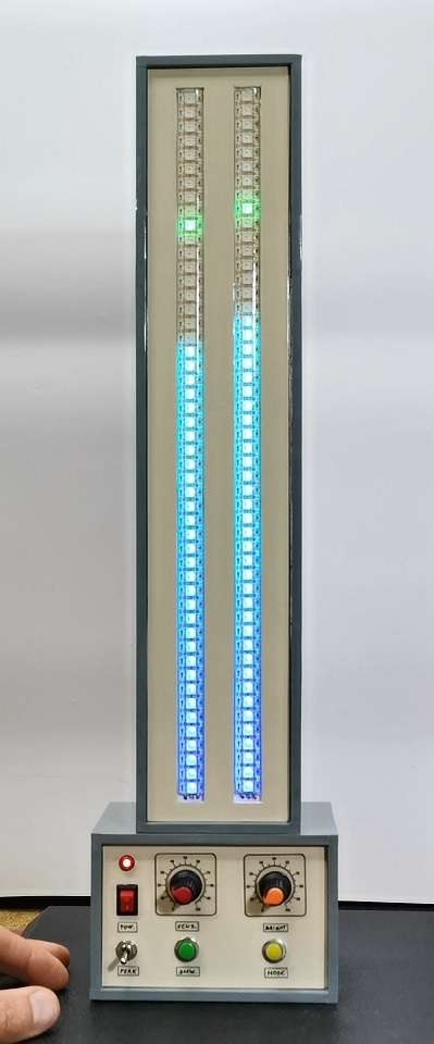
We can also place the box with the LED lights vertically above the control box, so we get a vertical audio visualizer VU meter.

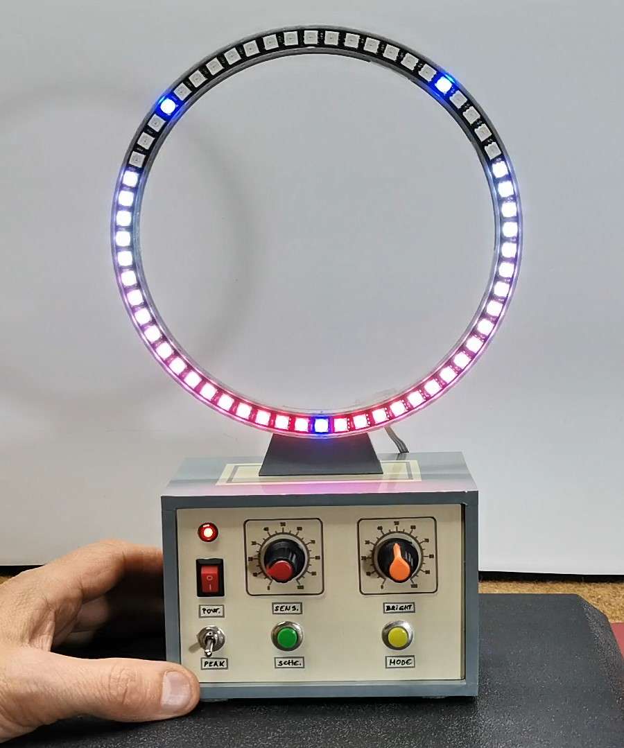
Next I would like to show you visually effective and very unusual way of displaying signal strength. Now instead of a led strip we will use a led ring with 60 diodes. Also in the code we need to deselect the line where is defined the VU meter on single LED strip.

And finally a short conclusion.
This is probably the most advanced LED VU meter for which you can find detailed documentation. Despite the many options and customization possibilities, it is extremely simple to make and contains a minimal number of components. Device is mounted in a suitable case made of PVC board with a thickness of 5 mm and covered with colored self-adhesive wallpaper.
