BLOCK DIAGRAM
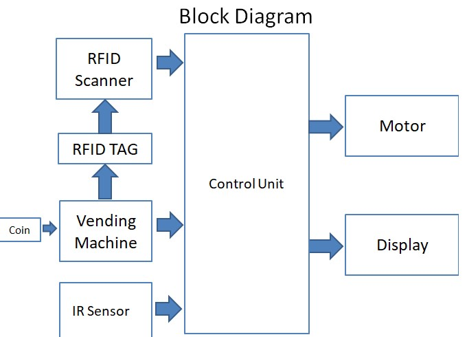
It consists of controller Microcontroller, Vending Machine, RFID module, Output Module, Power Supply, and Status Indicator.

RFID cards have diverse range of functions, while provides convenience, as the cards must simply be waived or tapped in front of a reader rather than swiped. These cards are used for applications as access control in security systems, time and attendance, network login security, biometric verification, cashless payment, and even event management.
An RFID reader is a device that is used to interrogate an RFID tag. The reader has an inbuilt antenna that emits radio waves; the tag responds by sends back its data.
Micro controller senses the signal given from switches and decides the mode of operation i.e. drive the motor of parking system. It fetches data from memory location and sends it to output devices like display, motor driver and buzzer. At the same time it can accept data from Keypad for recharging options and from IR receiver to sense that vehicle on parking pallets.
The display is various messages like valid card, invalid card, access allowed, manual access etc. We have used 16x2 alphanumeric displays.
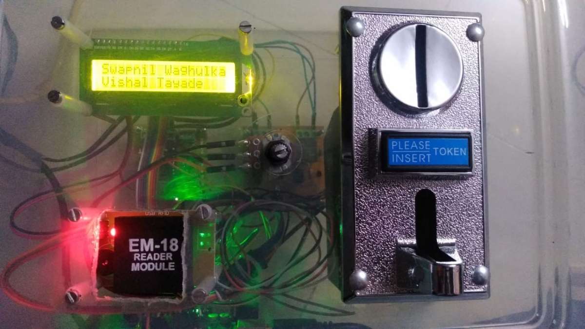
An Arduino base vending machine is used in the project. The vending machine is used for costing purpose. It is having RFID scanner on it to call the pallet having user’s vehicle.
An infrared sensor is an electronic instrument that is used to sense certain characteristics of its surroundings. It does this by either emitting or detecting infrared radiation. Infrared sensors are also capable of measuring the heat being emitted by an object and detecting motion.DC Motor is used to open the Gate. This will be done when user has successfully performed the RFID swap operation with sufficient balance.
CIRCUIT DIAGRAM

When the light emitted by the IR LED is incident on the photodiode after hitting an object, the resistance of the photodiode falls from a huge value. One of the inputs of the op – amp is at threshold value set by the potentiometer. The other input to the op-amp is from the photodiode’s series resistor.
When the incident radiation is more on the photodiode, the voltage drop across the series resistor will be high. In the IC, both the threshold voltage and the voltage across the series resistor are compared. If the voltage across the resistor series to photodiode is greater than that of the threshold voltage, the output of the IC Op – Amp is high. As the output of the IC is connected to an LED, it lightens up. The threshold voltage can be adjusted by adjusting the potentiometer depending on the environmental conditions. The IR sensors are then connected to relay board for further operations.
The next section is relay board. An opto-coupler is a device which encapsules an LED and a photo-transistor inside a hermetically sealed, water proof, light proof package in the form of an 8 pin IC (resembling a 555 IC). The LED is terminated over a couple of pin outs, while the three terminals of the photo-transistor are terminated over the other three assigned pin outs. The idea is simple, it's all about providing an input DC from the source which needs to be isolated to the LED pin outs via a limiting resistor (as we normally do with usual LEDs) and to switch the photo transistor in response to the applied input triggers.
FLOW CHART
Parking

Hardware

We implemented our very own circular car parking system which is used to park 4 cars at the same time. It is basically private car parking system. There are different types of material used to implement this car parking system such as:
- EN8
- Aluminum sheet
- Aluminum bars
EN8 material is selected on the basis of cost and its hardness. Aluminum sheets are used to create 4 pallets to park the cars and aluminum bars is used for pallet support.
VENDING MACHINE

SIMULATION

