
This project is for emergency Lighting System for home. In Solapur like City there is frequent load Shedding and in Rainy season, there is power cut happens and People need of Emergency lighting System, Nowadays Use of candles and Lantern are outdated. So Inverter is the Best option.
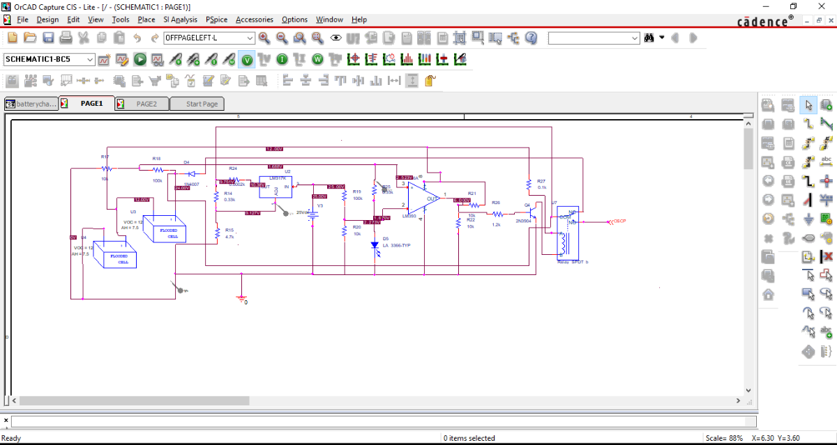
1st block of project is (TWO 7.5AH 12 volt) = TOTAL 24 VOLT battery charger
2nd block of the system is RC phase shift oscillator 64Hz.
In 3rd Block oscillation are stepped up by Transformer.
When Battery get charged Relay is Operated and charger is made switched off. When Mains Power is off oscillator is sourced by Battery and 5 Watt Lamp Glows.
TIP31 DARLINGTON pair is used to boost the current.
Step1
Two 7.5AH 12 VOLT Battery connected in Series. And charged by LM317 Charging circuitary.
TRANSFORMER used is 9-0-9 and full wave rectifier is implemented and 9 x2 =18 x 1.41=25 volts
LM317 Circuitary used as the battery charger. For 12 volt R15 value is 2.2k and for 24 volt R15 value is 4.7k.
Vout is calculated as shown in Equation 1. IADJ is typically 50 μA flows through terminal 1 of LM317 and negligible. R16 is 4.5k, Constant 120mA charging current is adjusted to charge the battery.
0.6 is Vbe Transistor Base To Emiter Voltage
R16=0.6/120mA = 4.7 ohms, I2R = 120mA x 120mA x 4.7 = 67 mWatt So 1/4 watt
7.5Ah/120mA = 62 hours to charge the each battery and Safer Side as no side effects because of over heat.
Initial Battery current is 2.2 Amp, but vout of LM317 is adjusted at 1.4 volt initially to avoide high Initial Current.
R14 IS 330 OHM 5WATT.
VO = VREF (1 + R15 / R14) + (IADJ × R15),
Vref is 1.25 volts.
Diode D4 prevents reverse current from Battery.
STEP 2
RC phase shift circuitary is implemented by BC639 NPN Transistor. 1/2x3.14x2.45 x1kohm x1uf = 64Hz oscilations. 64 Hz Oscillations are boosted by TIP31 Darlington Pair and is Stepped up By 6-0-6 / 2Amp Transformer used as a Step Up Transformer. 5 Watt Lamp is connected at Primary of 6-0-6 /2Amp TR.
1kohm precsion rotary pot is used is connected in series with 22ohm 1 watt Resistor to adjust the oscillations. RE is 1 Kohm 1 Watt, voltage across Re is fed to the Base of Darlington Pair, voltage across Re
is around 19 volt to 22 volt range.
Darlington pair is used to boost the current
Total Beat=Beta1 + Beat1 x Beta2 + Beat2 = 25 + 625 + 25 = 675 x IBtotal = Ic
Total Ic=2Amp,
SoTotal IB= Ic/Beat = 2Amp / 675 = 3 mA
RB= 19 volts at oscillator emitter then (19 volts - 1.8 volts ) / 3mA = near about 4.7 k ohm = RB
C13 is 470uF / 110 volts to minimise current and pass only AC.
.png)

Step 3
When Mains Power is OFF oscillator is Sourced by 7.5Ah x 2 Battery and Lamp Glows.
.jpeg)
.jpeg)
.jpeg)