Introduction
Graphical LCD has 128x64 pixels. It has 128 columns and 64 row segments.
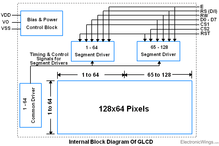
- It uses two display segment drivers. Since segment driver has 64 channel, GLCD module contains two segment drivers to drive 128 column segments.
- It has one common driver which drives 64 row segments as well as it generates clock and control signals for two segment drivers as shown in figure below.
GLCD 128x64 Pin Diagram
GLCD module JHD12864E has 20 pins as shown in below figure.
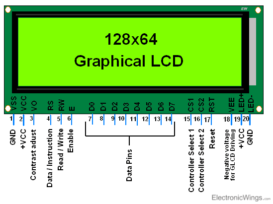
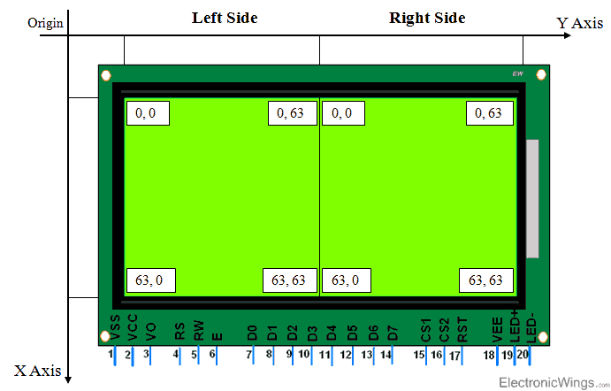
Since it has two segment drivers to drive 128 column segments, GLCD splits into two parts i.e. Left side and Right side. It has 20 pins. Following table will show pin description with their functions.
| Pin No. | Symbol | Description | Function |
| 1 | VSS | Ground | 0V |
| 2 | VDD | Power Supply for Logic Circuit | +5V |
| 3 | VO | LCD Contrast Adjustment | Contrast Control |
| 4 | RS | Instruction/Data Register Selection | RS = 0: Instruction Register RS = 1: Data Register |
| 5 | R/W | Read/Write Selection | R/W = 0: Write R/W = 0: Read |
| 6 | E | Enable Signal | |
| 7 – 14 | DB0–DB7 | Data Input/output Lines | 8 – Bit |
| 15 | CS1 | Chip (Seg. Driver) Selection | CS1 = 1: Select Chip1 |
| 16 | CS2 | Chip (Seg. Driver) Selection | CS2 = 1: Select Chip2 |
| 17 | RST | Reset Signal | RST = 0: Display OFF, Display from Line 0 |
| 18 | VEE | Negative Voltage for LCD Driving | -10 V |
| 19 | LED+ | Supply Voltage for Led+ | +5V |
| 20 | LED- | Supply Voltage for Led- | 0V |
Writing to GLCD 128x64
Let’s see how to write to Graphical LCD. It needs to know where data gets displayed on GLCD. Figure given shows where and how D0-D7 data will be seen on display.
Above figure shows X (Row) and Y (Column) address to select location for data write. Two controllers control each half of display. Each half of display has vertical 64 pixels’ addresses which are accessed by Y address from 0x40 to 0x7F. These two controllers alternatively selected by CS1 and CS2 pins to select either half of display for write,
- To select left half of display we need to make CS1 = 1, CS2 = 0.
- To select right half of display we need to make CS1 = 0, CS2 = 1.
X address is shown in above figure as page 0 – 7. Each page contains 8 rows.
Display Data on GLCD
To display data on LCD we need to write it on LCD data pins. After providing proper address we can send data to GLCD. Data value is directly mapped by pixels to glow. Accordingly, we need to send data.
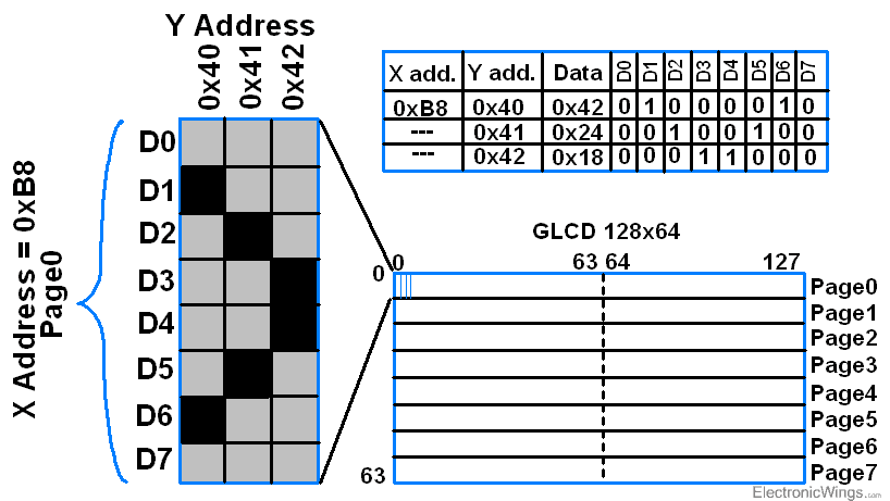
Above figure shows data print on GLCD for which,
- We need to set Y address from where we need to write i.e. here it is from first location, so address is 0x40.
- Then we need to set X address to first page i.e. 0xB8.
- And write data as shown in above figure to data pins. It will print as in figure.
Instructions for JHD12864E GLCD
| No. | Instruction | RS | R/W | DB7 | DB6 | DB5 | DB4 | DB3 | DB2 | DB1 | DB0 | Function |
| 1 | Display ON/OFF | 0 | 0 | 0 | 0 | 1 | 1 | 1 | 1 | 1 | 0/1 | Controls Display ON/OFF 0=OFF 1=ON |
| 2 | Set Y Address | 0 | 0 | 0 | 1 | Y address (0 - 63) | Sets the Y Address | |||||
| 3 | Set Page (X Address) | 0 | 0 | 1 | 0 | 1 | 1 | 1 | Page (0 - 7) | Sets X Address | ||
| 4 | Set Display Start Line (Z Address) | 0 | 0 | 1 | 1 | Display Start Line (0 - 63) | Sets Display Start Line | |||||
| 5 | Status Read | 0 | 1 | Busy | 0 | ON/OFF | Reset | 0 | 0 | 0 | 0 | Read Status Busy: 0=Ready 1=Busy ON/OFF: 0=Display ON 1=Display OFF Reset: 0=Normal 1=Reset |
| 6 | Write Display Data | 1 | 0 | Write Data | Writes data into display data RAM. After writing instruction, Y Address incremented by 1 automatically | |||||||
| 7 | Read Display Data | 1 | 1 | Read Data | Reads data from display data RAM to data bus | |||||||
Display ON/OFF
Display data control instruction controls Display ON/OFF function. It is used to display data in RAM on Screen. It is controlled by DB0 bit as shown in above table.
1 = Display data on screen.
0 = Not display data on screen.
Set Y Address
Y Address of display data RAM is set in Y Address counter. Whenever write/read operation is executed, Y Address counter gets automatically incremented by one.
Set X Address (Page)
X Address (page) of display data RAM needs to be set in X Address Register. Here, user needs to increment page through program after every Y Address overflow occurs on current page. Note that if X Address (page) is not incremented after Y Address overflow occurs, then overwrite will occur on current page.
Set Display Start Line (Z Address)
Z Address of display data RAM is set in Display Start Line Register. It is used to set row (0 - 63) line from where data will be displayed on screen. Usually it sets to 0 i.e. data will be displayed from 0th (first line) top start line.
Status Read
This instruction is used to read status of GLCD.
Busy: Busy Status
1 = Device is busy in executing internal operation. No instruction will be accepted.
0 = Device is ready to accept instruction.
ON/OFF: Display ON/OFF Status
1 = Display ON
0 = Display OFF
Reset: Reset Status
1 = Shows system is being initialized. No instruction will be accepted except Status Read instruction.
0 = System is in usual operation condition.
Write Display Data
This instruction writes 8-bit data into display data RAM.
Read Display Data
This instruction reads 8-bit data from display data RAM.
GLCD Considerations
As there are different types of GLCD modules available in market,
- It is important to check the datasheet for GLCD modules.
- Each has different pin configuration and specifications.
- Incorrect connections are the most common cause for problems.
- Care should be taken for power pins as incorrect wiring can damage module.
- Check instructions timing values from datasheet.
Initialization
To initialize the display, we need to do steps given below,
- Send Display OFF command i.e. 0x3E
- Send Y address e.g. here 0x40 (Start address).
- Send X address (Page) e.g. here 0xB8 (Page0).
- Send Z address (Start line) e.g. here 0xC0 (from 0th line).
- Now send Display ON command i.e. 0x3F
Command Write
To write command, we need to do steps given below,
- Send command on data pins.
- Make RS = 0 (Command Register) and RW = 0 (Write Operation).
- Make High to Low transition on Enable pin of minimum 1 us period.
Data Write
To write data, we need to do steps given below,
- Send Data on data pins.
- Make RS = 1 (Data Register) and RW = 0 (Write Operation).
- Make High to Low transition on Enable pin of minimum 1us period.
Displaying Image
Let’s see how to display image on GLCD. We can display binary image up to 128x64 pixel resolution. Binary image means each pixel has only two values i.e. 0 or 1. So here in GLCD 128x64, either that pixel will be ON or OFF.
- First, we need to know that GLCD 128x64 JHD12864E can display only Binary image.
- So, we need to convert image into binary format to display it on GLCD.
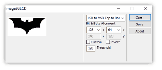
- There are several ways to do this, we will use Image2GLCD application.
- Image2GLCD application converts JPG, GIF, BMP, PNG format image files to binary format.
- This application creates binary data to represent image on GLCD.
- As shown in below snap of application, click on Open to select image from drive and Save data.
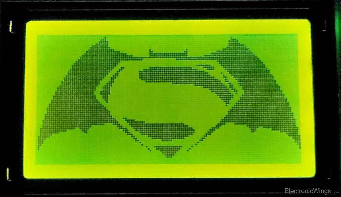
- And now you have saved binary image data to print on GLCD. Simply write it to GLCD and see your image on GLCD.
You can download Image2GLCD application from below attachments.
Output Displayed On GLCD 128x64
Programming and interfacing of GLCD with 8 bit Controllers with example is given below.
Examples of GLCD 128x64 interfacing
Components Used |
||
|---|---|---|
| GLCD 128x64 GLCD 128x64 is a Graphical LCD having 128x64 pixel resolution. It is used to display values, text with different fonts, binary images, animation, custom character. |
X 1 | |
Downloads |
||
|---|---|---|
|
|
Image2GLCD application | Download |