The MSP-EXP430G2 was the first LaunchPad kit by TI (Texas Instruments) and is fairly popular among the masses.
The MSP-EXP430G2 boards can be programmed using either Code Composer Studio or the Energia IDE.
This board can be used with any 14 or 20 pin DIP MSP430 IC.
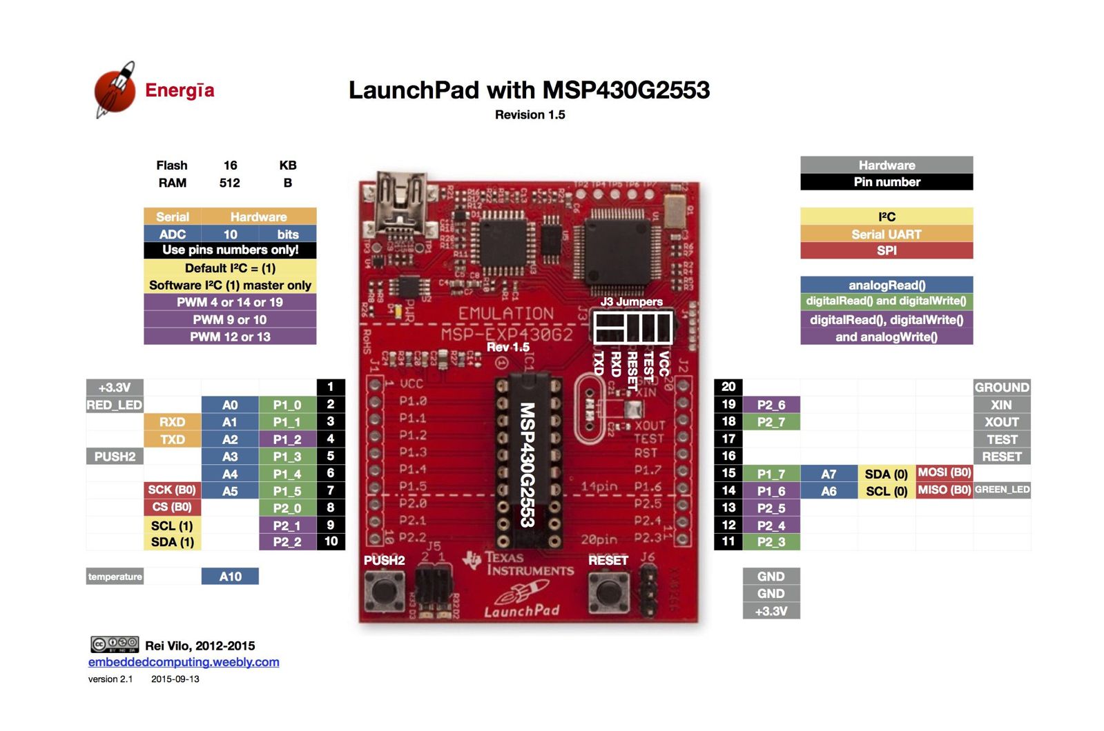
The above image shows the MSP-EXP430G2 board with an MSP430G2553 IC. The image has been taken from one of the posts on the discussion at GitHub. Here is a link to the discussion page: https://github.com/energia/Energia/issues/486
The image shows an extra pair of I2C pins ( SCL(1) and SDA(1) ). These pins are the SCL and SDA pins for the software I2C implementation used by Energia IDE in its revisions 17 and 18.
When the board is used with an MSP430G2553 IC, it offers 16kB of Flash memory and 512Bytes of RAM.
16 GPIO pins are available for use. All 16 pins can be used as Digital I/O pins. 8 pins can be used as Analog Input pins (A0-A7 in the image given above).
7 PWM pins are available. Pins 4, 9, 10, 12, 13, and 19 (in the image given above) are the PWM pins. 4 or 14 or 19, only one can be used as a PWM pin at a time. Similarly 9 or 10, only one can be used as a PWM pin at a time. The same goes for 12 or 13, only one can be used as a PWM pin at a time.
For Energia users, you can refer to a pin in 2-3 different ways. For example, while referring to pin P1.3 of the IC, we can use P1_3 or 5 or A3 or PUSH2 (cannot use P1.4).
The board is powered using a USB mini B cable.
Note: The VCC available on the board is 3.3V. If you need 5V supply, you will need to use some other source.
Word of Caution: The MSP430 ICs are 3.3V ICs. So, do not input a 5V signal directly to the I/O pins. Use a level converter or a simple voltage divider to convert the 5V signal to 3.3V. If this is not done, there are chances that you may fry that pin.
Note: For this board, it is possible to use only Software UART or Hardware UART at a time. We cannot use both at the same time. Also, jumper connections need to be changed for changing the UART configuration (Software or Hardware). The jumpers associated with UART can be found at J3 on the board (A bunch of jumpers present just above pin 20). How to place the jumpers is shown in white text on the board near J3.
Components Used |
||
|---|---|---|
| TI Launchpad MSP-EXP430G2 TI Launchpad MSP-EXP430G2 |
X 1 | |