The hardware connection details for the reference design board.
The iMOTIONTM link cable is needed to bridge the PC/debugger side and motor drive system (the target iMOTION™ device, hot side) with 1 kV DC galvanic isolation. Users can go to Section 5.3 for more information on the iMOTIONTM link.
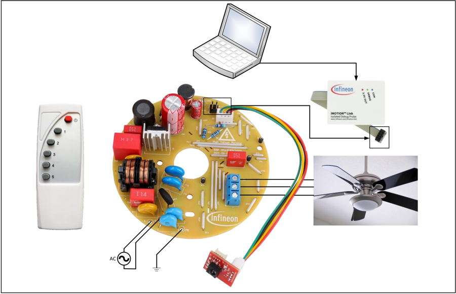
- Connect iMOTIONTM link’s 8-pin cable to main board J1 using the default pin order (only pin 5~8 are used), and connect PC and iMOTIONTM link with the USB wire.
- Then connect AC power supply (L, N, PE) and the motor (J3).
- Connect main board J2 to daughter board J1 by cable attached in package box.
Hardware connection
For software part refer the user manual, click here.