In this guide, we will see how to program GPIOs.
nRF52840 Development kit has 4 user programable LEDs and Buttons built-in. We will begin with Blinking those 4 LEDs.
LED Blinking
To make things simple, we can go to the folder: C:\nRF5_SDK\v17.0.2\examples
You can find various example programs in the same folder. Explore each folder to get the idea about examples, especially explore peripheral folder examples.
Here we are using nRF52840 DK, PCA10056, with SES IDE, so for LED blinking go to C:\nRF5_SDK\v17.0.2\examples\peripheral\blinky\pca10056\blank\ses and open EW PROJECT FILE, which should launch SES IDE, and load the blinky project.
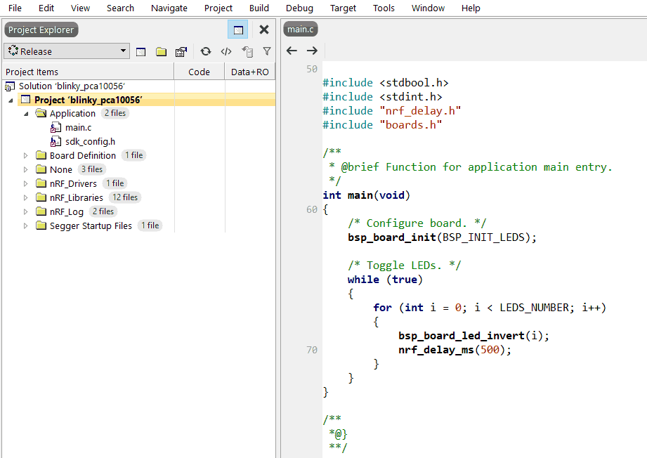
Now Open main.c file under Application folder in the SES project file explorer on left.
Click on Build>> Build blinky_pca10056, It will build it successfully.
Make sure the USB of the kit is connected.
- Then go to Target >> Connect J-Link
- Target >> Erase All
- Target>> Download blinky_pca10056
Check on the Board for LED Blinking. We will follow this process for all the examples onward.
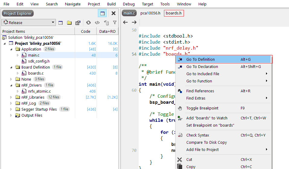
You can explore the detailed code behind each function, header file by right-clicking on it and >> Go To Definition.
Also, you can browse through the various files on the top list by clicking on the file or arrow key.
Understanding Code
1. Take a look at “boards.h” file, you will find#include “pca10056.h highlighted, if you go in this file, you will find all the pin numbers are defined here.
For example, LED’s and Button PINs
#define BSP_LED_0      13
#define BSP_LED_1      14
#define BSP_LED_2      15
#define BSP_LED_3      16

#define BUTTONS_NUMBER 4

#define BUTTON_1       11
#define BUTTON_2       12
#define BUTTON_3       24
#define BUTTON_4       25
2. Further in “boards.h” you will find LED and buttons related definitions and functions.
Code
In main(), we have this function bsp_board_led_invert(i);, this function is the responsible for the LED state inverting.
let's see the code behind it using the SES Go to Definition feature.
This will open the boards.c file, and you can see the code behind that function there. So this is the function that actually gets executed nrf_gpio_pin_toggle(m_board_led_list[led_idx]).
------------------------------------
The above example uses a function defined in the “boards.h”.
Using GPIO Functions
Now, without using boards.h, we can blink LEDs using GPIO settings as follow.
The program will blink the led connected on pin no. 13 with a 100ms delay.
#include <stdbool.h>
#include <stdint.h>
#include "nrf_delay.h"
#include "nrf_gpio.h"

#define led 13   // onboard LED is connected on Pin 13

int main(void)
{
    nrf_gpio_cfg_output(led); //configure led pin as output

    while (true)
    {
        nrf_gpio_pin_set(led);  // Turn LED OFF
        nrf_delay_ms(100);
        nrf_gpio_pin_clear(led);// Turn LED ON
        nrf_delay_ms(100);
    }
}
Reading GPIO as input: Button Interface
Program to read the button and turn ON the LED, till the button pressed.
On-Board buttons are connected to GROUND, which means when the button gets pressed it will connect ground to the GPIO pin. When the button not presses, Pin is in the open state, to make it HIGH, we need to use internal PULL UP via ”nrf_gpio_cfg_input” function.
#include <stdbool.h>
#include <stdint.h>
#include "nrf_delay.h"
#include "nrf_gpio.h"

#define led 13
#define Button 12

int main(void)
{
    nrf_gpio_cfg_output(led); //configure led pin as output
    nrf_gpio_cfg_input(Button,NRF_GPIO_PIN_PULLUP);// configures button as input Pin

    nrf_gpio_pin_set(led);  //Turn OFF the LED

    while (true)
    {
        if(nrf_gpio_pin_read(Button)==0)  //Read GPIO
        nrf_gpio_pin_clear(led);   //Turn ON the LED

        else
        nrf_gpio_pin_set(led);   //Turn OFF the LED
    }
}
Useful GPIO Functions
nrf_gpio_range_cfg_output (uint32_t pin_range_start, uint32_t pin_range_end);
//Function for configuring the GPIO pin range as output pins.

nrf_gpio_range_cfg_input (uint32_t pin_range_start, uint32_t pin_range_end, nrf_gpio_pin_pull_t pull_config)
/*Function for configuring the GPIO pin range as input pins.
1st Parameter:
pin_number can be equal to: 0 to 31 // (number)

2nd Parameter:
pull_config can be equal to any of these values:
•NRF_GPIO_PIN_PULLUP
•NRF_GPIO_PIN_PULLDOWN
•NRF_GPIO_PIN_NOPULL
for e.g:
 nrf_gpio_cfg_input(13,NRF_GPIO_PIN_NOPULL); // Configure Pin 13 as input with no internal pull_up resistor
*/

nrf_gpio_cfg_output (uint32_t pin_number)
//Function for configuring the given GPIO pin number as output.

nrf_gpio_cfg_input (uint32_t pin_number, nrf_gpio_pin_pull_t pull_config)
//Function for configuring the given GPIO pin number as input.

nrf_gpio_pin_toggle (uint32_t pin_number)
//Function for toggling a GPIO pin

nrf_gpio_pin_write (uint32_t pin_number, uint32_t value)
/*Function for writing a value to a GPIO pin. Pin must be configured as output. If value is 0, it
clears the pin and >=1 Sets the pin.*/

nrf_gpio_pin_read (uint32_t pin_number)
//Function for reading the input level of a GPIO pin.
For further details refer to the Documentation
Note: Instead of making changes in the example program, You can also create a new folder e.g. “My Projects” in C:\nRF5_SDK\v17.0.2\examples so you can copy-paste any example in the “My Project” folder, and edit, change it.
Components Used |
||
|---|---|---|
| nRF52840-DK nRF52840-DK |
X 1 | |
| NRF52-DK NRF52-DK |
X 1 | |