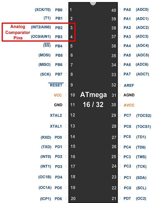
Introduction to Analog Comparator
- ATmega16/ATmega32 based on AVR has two pins for analog voltage compare i.e. AIN0 and AIN1. AIN0 is the positive terminal whereas AIN1 is the negative terminal.
- When the voltage on positive pin AIN0 is higher than negative pin AIN1, the ACO bit of ACSR register is set.
- It is possible to use ADC channels (PA0 to PA7) as a negative terminal (AIN1) of a comparator. In this condition, AIN1 will not be considered as a negative input to the comparator. ADC multiplexer is used to select the ADC channel to be connected. ADC must be switched off to use this feature.
It means it is possible to compare nine analog signals with one positive analog signal, sequentially but not simultaneously.
Pins of Analog Comparator
The register configurations for analog comparator are explained below.
SFIOR: Special Function IO Register
| ADTS2 | ADTS1 | ADTS0 | ADHSM | ACME | PUD | PSR2 | PSR10 |
|---|
Bit 3 – ACME: Analog Comparator Multiplexer Enable
When the ACME bit is one and the ADC is switched off, the ADC multiplexer selects the input connected at ADC channels as a negative input to the Analog Comparator and AIN1 is not considered for negative input to the comparator. When the ACME bit is zero, AIN1 acts as the negative terminal of the Analog Comparator.
ACSR: Analog Comparator Control and Status Register
| ACD | ACBG | ACO | ACI | ACIE | ACIC | ACIS1 | ACIS0 |
|---|
Bit 7 – ACD: Analog Comparator Disable
When ACD is one, then the power to the Analog Comparator is switched Off. That means analog comparator is disabled.
Bit 6 – ACBG: Analog Comparator Bandgap Select
When ACBG is one, then the bandgap reference voltage replaces the positive input to the analog comparator.
When ACBG is zero, then AIN0 is applied to the positive of the analog comparator.
Bit 5 – ACO: Analog Comparator Output
This bit indicates the output of the comparator, when AIN0 voltage is higher than the negative pin voltage then the ACO bit is set, otherwise it is clear.
Bit 4 – ACI: Analog Comparator Interrupt Flag
ACI bit is set by hardware. When a comparator output event triggers, the interrupt mode is defined by ACIS1 and ACIS0. The Analog Comparator Interrupt routine is executed if the ACIE bit is set and the I-bit in SREG is set. ACI is cleared by hardware when executing the corresponding interrupt handling vector. Alternatively, ACI is cleared by writing a logic one to the flag.
Bit 3 – ACIE: Analog Comparator Interrupt Enable
When the ACIE bit set to one and the I-bit in the Status Register is set, the Analog Comparator Interrupt is activated. When set to zero, the interrupt is disabled.
Bit 2 – ACIC: Analog Comparator Input Capture Enable
When ACIC set to one, this bit enables the Input Capture function in Timer/Counter1 to be triggered by the Analog Comparator. When Set to zero, the connection between Analog Comparator and Input Capture function does not exist.
Bit 1:0 - ACIS1:ACIS0: Analog Comparator Interrupt Mode Select
| ACIS1 | ACIS0 | Interrupt Mode |
|---|---|---|
| 0 | 0 | Comparator Interrupt on Output Toggle |
| 0 | 1 | Reserved |
| 1 | 0 | Comparator Interrupt on Falling Output Edge |
| 1 | 1 | Comparator Interrupt on Rising Output Edge |
ADMUX: ADC Multiplexer Selection Register
| REFS1 | REFS0 | ADLRA | MUX4 | MUX3 | MUX2 | MUX1 | MUX0 |
|---|
Bit 2:0 – MUX2: MUX0 – To select the ADC input (from ADC0 to ADC7) for the negative input of the comparator.
| ACME | ADEN | MUX2.0 | Analog Comparator Negative Input |
|---|---|---|---|
| 0 | x | xxx | AIN1 |
| 1 | 1 | xxx | AIN1 |
| 1 | 0 | 000 | ADC0 |
| 1 | 0 | 001 | ADC1 |
| 1 | 0 | 010 | ADC2 |
| 1 | 0 | 011 | ADC3 |
| 1 | 0 | 100 | ADC4 |
| 1 | 0 | 101 | ADC5 |
| 1 | 0 | 110 | ADC6 |
| 1 | 0 | 111 | ADC7 |
ATmega16/32 Analog Comparator Circuit diagram
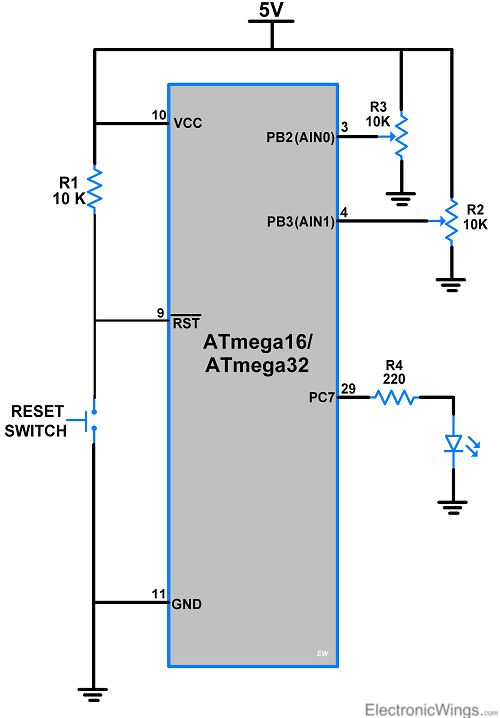
- In the above circuit diagram, the two input signals are connected to the AIN0 and AIN1 pins of PORTB.
- The output of the comparator is shown by the LED which is connected to the PC7 pin (Pin No. 29).
- When the AIN0 pin voltage is greater than the AIN1 pin voltage then the output LED will glow, otherwise LED will off.
Programming of ATmega16/32 Analog Comparator
Programming steps for taking negative input from AIN1
- Enable AIN1 for negative input, by clearing ACME bit of SFIOR register
- Clear ACSR register.
- Monitor ACO bit of ACSR register, and take decision accordingly.
ATmega16/32 Analog Comparator Program
/*
 * ATmega16_Analog_Comparator.c
 *
 * http://www.electronicwings.com
 */

#define F_CPU 8000000UL
#include <avr/io.h>
#include <util/delay.h>

int main()
{
	DDRC |= 0x80;		/* Make pin 7 of PORTC is output */
	SFIOR &= (1<<ACME);	/* Enable AIN1 for -ve input */
	ACSR &= 0x00;		/* Clear ACSR register */

	while(1)
	{
		if (ACSR & (1<<ACO))/* Check ACO bit of ACSR register */
		PORTC = 0x80;	/* Turn ON PC7 pin */
		else		/* If ACO bit is zero */
		PORTC = 0x00;	/* Then	turn OFF PC7 pin */
	}
}
Programming steps to take negative input from ADC channel
- Disable ADC by clearing ADEN bit of ADCSRA register
- Select the ADC pin by setting the ADMUX register.
- Enable ADC for negative input, by setting ACME bit of SFIOR register
- Clear ACSR register.
- Monitor ACO bit of ACSR register, and take a decision as per requirement.
ATmega16/32 Analog Comparator using ADC Program
/*
 * ATmega16_analog_comparator_using_ADC.c
 *
 * http://www.electronicwings.com
 */

#define F_CPU 8000000UL
#include <avr/io.h>
#include <util/delay.h>

int main()
{
	DDRC |= 0x80;		/* Make pin 7 of PORTC as output */
	ADCSRA &= (1<<ADEN);	/* Disable ADC */
	ADMUX = 0x00;		/* Select ADC0 as a -ve pin of comparator */
	SFIOR |= (1<<ACME);	/* Enable analog comparator */
	ACSR = 0x00;		/* Clear ACSR resister */

	while(1)
	{
		if (ACSR & (1<<ACO))/* Check ACO bit of ACSR register */
		PORTC = 0x80;	/* Turn ON PC7 pin */
		else		/* If ACO bit is zero */
		PORTC = 0x00;	/* Then	turn OFF PC7 pin */
	}

}
Video
Components Used |
||
|---|---|---|
| ATmega 16 ATmega 16 |
X 1 | |
| Atmega32 Atmega32 |
X 1 | |
| LED 5mm LED 5mm |
X 1 | |
| Breadboard Breadboard |
X 1 | |