Introduction
The Serial Peripheral Interface (SPI) is a bus interface connection protocol originally started by Motorola Corp. It uses four pins for communication.
- SDI (Serial Data Input)
- SDO (Serial Data Output)
- SCLK (Serial Clock)
- CS (Chip Select)
It has two pins for data transfer called SDI (Serial Data Input) and SDO (Serial Data Output). SCLK (Serial Clock) pin is used to synchronize data transfer and Master provides this clock. CS (Chip Select) pin is used by the master to select the slave device.

SPI devices have 8-bit shift registers to send and receive data. Whenever a master needs to send data, it places data on the shift register and generates a required clock. Whenever a master wants to read data, the slave places the data on the shift register and the master generates a required clock. Note that SPI is a full-duplex communication protocol i.e. data on master and slave shift registers get interchanged at the same time.
ATmega16 SPI Communication
ATmega16 has an inbuilt SPI module. It can act as a master and slave SPI device. SPI communication pins in AVR ATmega are:
- MISO (Master In Slave Out)
The Master receives data and the slave transmits data through this pin.
- MOSI (Master Out Slave In)
The Master transmits data and the slave receives data through this pin.
- SCK (Shift Clock)
The Master generates this clock for the communication, which is used by the slave.
The only master can initiate a serial clock.
- SS (Slave Select)
Master can select slaves through this pin.
The interconnection between master and slave using SPI is shown in the below figure.

ATmega16/32 SPI Communication Pins
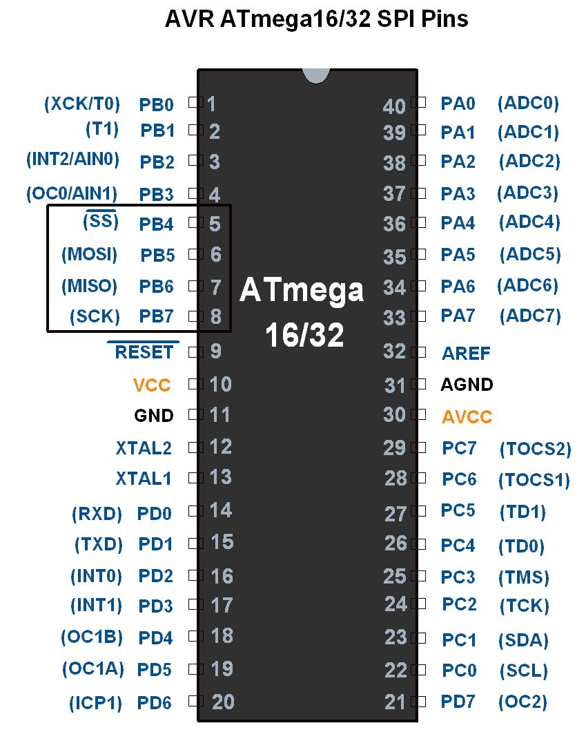
SPI Pins Configurations
| SPI Pins | Pin No. on ATmega16 chip | Pin Direction in master mode | Pin Direction in slave mode |
|---|---|---|---|
| MISO | 7 | Input | Output |
| MOSI | 6 | Output | Input |
| SCK | 8 | Output | Input |
| SS | 5 | Output | Input |
AVR ATmega16 uses three registers to configure SPI communication that are SPI Control Register, SPI Status Register and SPI Data Register.
Let’s see these Registers.
SPCR: SPI Control Register

Bit 7 – SPIE: SPI Interrupt Enable bit
1 = Enable SPI interrupt.
0 = Disable SPI interrupt.
Bit 6 – SPE: SPI Enable bit
1 = Enable SPI.
0 = Disable SPI.
Bit 5 – DORD: Data Order bit
1 = LSB transmitted first.
0 = MSB transmitted first.
Bit 4 – MSTR: Master/Slave Select bit
1 = Master mode.
0 = Slave Mode.
Bit 3 – CPOL: Clock Polarity Select bit
1 = Clock start from logical one.
0 = Clock start from logical zero.
Bit 2 – CPHA: Clock Phase Select bit
1 = Data sample on trailing clock edge.
0 = Data sample on the leading clock edge.
Bit 1:0 – SPR1: SPR0 SPI Clock Rate Select bits
The below table shows the SCK clock frequency select bit setting.
| SPI2X | SPR1 | SPR0 | SCK Frequency |
|---|---|---|---|
| 0 | 0 | 0 | Fosc/4 |
| 0 | 0 | 1 | Fosc/16 |
| 0 | 1 | 0 | Fosc/64 |
| 0 | 1 | 1 | Fosc/128 |
| 1 | 0 | 0 | Fosc/2 |
| 1 | 0 | 1 | Fosc/8 |
| 1 | 1 | 0 | Fosc/32 |
| 1 | 1 | 1 | Fosc/64 |
SPSR: SPI Status Register

Bit 7 – SPIF: SPI interrupt flag bit
- This flag gets set when the serial transfer is complete.
- Also gets set when the SS pin is driven low in master mode.
- It can generate an interrupt when SPIE bit in SPCR and a global interrupt is enabled.
Bit 6 – WCOL: Write Collision Flag bit
- This bit gets set when SPI data register writes occurs during previous data transfer.
Bit 5:1 – Reserved Bits
Bit 0 – SPI2X: Double SPI Speed bit
- When set, SPI speed (SCK Frequency) gets doubled.
SPDR: SPI Data Register

- SPI Data register used to transfer data between the Register file and SPI Shift Register.
- Writing to the SPDR initiates data transmission.
When the device is in master mode
- Master writes data byte in SPDR. Writing to SPDR starts data transmission.
- 8-bit data starts shifting out towards slave and after the complete byte is shifted, SPI clock generator stops, and SPIF bit gets set.
When the device is in slave mode
- THE Slave SPI interface remains in sleep as long as the SS pin is held high by the master.
- It activates only when the SS pin is driven low. Data is shifted out with incoming SCK clock from master during a write operation.
- SPIF is set after the complete shifting of a byte.
SS pin functionality Master mode
- In master mode, the SS pin is used as a GPIO pin.
- Make the SS pin direction as output to select a slave device using this pin.
- Note that if the SS pin configured as input then it must be set high for master operation.
- If it is set as input in master mode and gets driven low by an external circuit, then the SPI system recognizes this as another master selecting SPI as a slave due to its active low behavior.
- This will clear the MSTR bit in the SPCR register and SPI turns in slave mode.
SS pin functionality Slave mode
- In slave mode, the SS pin is always configured as an input.
- When it is low SPI activates.
- And when it is driven high SPI logic gets reset and does not receive any incoming data.
Example
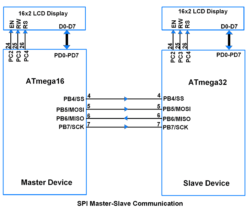
Let’s do SPI communication using AVR family-based ATmega16 (Master) and ATmega32 (Slave). Master will send continuous count to Slave. Display the sent and received data on 16x2 LCD.
ATmega16/32 SPI Interfacing diagram
Let’s first program the Master device i.e. ATmega16
SPI Master Initialization steps
To initialize ATmega16 as Master, do the following steps
- Make MOSI, SCK, and SS pins directions as output.
- Make MISO pin direction as input.
- Make SS pin High.
- Enable SPI in Master mode by setting SPE and MSTR bits in the SPCR register.
- Set SPI Clock Rate Bits combination to define SCK frequency.
SPI_Init function
void SPI_Init()					/* SPI Initialize function */
{
	DDRB |= (1<<MOSI)|(1<<SCK)|(1<<SS);	/* Make MOSI, SCK, SS
						as Output pin */
	DDRB &= ~(1<<MISO);			/* Make MISO pin
						as input pin */
	PORTB |= (1<<SS);			/* Make high on SS pin */
	SPCR = (1<<SPE)|(1<<MSTR)|(1<<SPR0);	/* Enable SPI in master mode
						with Fosc/16 */
	SPSR &= ~(1<<SPI2X);			/* Disable speed doubler */
}
SPI Master Write steps
- Copy data to be transmitted in the SPDR register.
- Wait until the transmission is complete i.e. poll SPIF flag to become High.
- While the SPIF flag gets set read SPDR using a flush buffer.
- SPIF bit is cleared by H/W when executing the corresponding ISR routine.
- Note that to clear the SPIF bit, need to read SPIF and SPDR registers alternately.
SPI_Write function
Input argument: It has an input argument of data to be transmitted.
void SPI_Write(char data)		/* SPI write data function */
{
	char flush_buffer;
	SPDR = data;			/* Write data to SPI data register */
	while(!(SPSR & (1<<SPIF)));	/* Wait till transmission complete */
	flush_buffer = SPDR;		/* Flush received data */
/* Note: SPIF flag is cleared by first reading SPSR (with SPIF set) and then accessing SPDR hence flush buffer used here to access SPDR after SPSR read */
}
SPI Master Read steps
- Since writing to SPDR generates SCK for transmission, write dummy data in the SPDR register.
- Wait until the transmission is completed i.e. poll SPIF flag till it becomes High.
- While the SPIF flag gets set, read requested received data in SPDR.
SPI_Read function
Return value: It returns the received char data type.
char SPI_Read()				/* SPI read data function */
{
	SPDR = 0xFF;
	while(!(SPSR & (1<<SPIF)));	/* Wait till reception complete */
	return(SPDR);			/* Return received data */
}
Program for SPI Master device
/*
 * ATmega16_Master.c
 * http://www.electronicwings.com
 */


#define F_CPU 8000000UL			/* Define CPU Frequency 8MHz */
#include <avr/io.h>			/* Include AVR std. library file */
#include <util/delay.h>			/* Include Delay header file */
#include <stdio.h>			/* Include Std. i/p o/p file */
#include <string.h>			/* Include String header file */
#include "LCD_16x2_H_file.h"		/* Include LCD header file */
#include "SPI_Master_H_file.h"		/* Include SPI master header file */

int main(void)
{
	uint8_t count;
	char buffer[5];

	LCD_Init();
	SPI_Init();

	LCD_String_xy(1, 0, "Master Device");
	LCD_String_xy(2, 0, "Sending Data:    ");
	SS_Enable;
	count = 0;
	while (1)			/* Send Continuous count */
	{
		SPI_Write(count);
		sprintf(buffer, "%d   ", count);
		LCD_String_xy(2, 13, buffer);
		count++;
		_delay_ms(500);
	}

}
Now Program for Slave device i.e. ATmega32
SPI Slave Initialization steps
- Make MOSI, SCK, and SS pins direction of the device as input.
- Make MISO pin direction of the device as output.
- Enable SPI in slave mode by setting SPE bit and clearing MSTR bit.
SPI_Init function
void SPI_Init()					/* SPI Initialize function */
{
	DDRB &= ~((1<<MOSI)|(1<<SCK)|(1<<SS));  /* Make MOSI, SCK, SS as
 						input pins */
	DDRB |= (1<<MISO);			/* Make MISO pin as
						output pin */
	SPCR = (1<<SPE);			/* Enable SPI in slave mode */
}
SPI Slave transmit steps
It has the same function and steps as we do SPI Write in Master mode.
SPI Slave Receive steps
- Wait until SPIF becomes High.
- Read received data from the SPDR register.
SPI_Receive function
Return value: it returns received char data type.
char SPI_Receive()			/* SPI Receive data function */
{
	while(!(SPSR & (1<<SPIF)));	/* Wait till reception complete */
	return(SPDR);			/* Return received data */
}
Program for SPI Slave device
/*
 * ATmega32_SPI_Slave.c
 * http://www.electronicwings.com
 */


#define F_CPU 8000000UL			/* Define CPU Frequency 8MHz */
#include <avr/io.h>			/* Include AVR std. library file */
#include <util/delay.h>			/* Include Delay header file */
#include <stdio.h>			/* Include std. i/p o/p file */
#include <string.h>			/* Include string header file */
#include "LCD_16x2_H_file.h"		/* Include LCD header file */
#include "SPI_Slave_H_file.h"		/* Include SPI slave header file */

int main(void)
{
	uint8_t count;
	char buffer[5];

	LCD_Init();
	SPI_Init();

	LCD_String_xy(1, 0, "Slave Device");
	LCD_String_xy(2, 0, "Receive Data:    ");
	while (1)			/* Receive count continuous */
	{
		count = SPI_Receive();
		sprintf(buffer, "%d   ", count);
		LCD_String_xy(2, 13, buffer);
	}

}
Video
Components Used |
||
|---|---|---|
| ATmega 16 ATmega 16 |
X 2 | |
| Atmega32 Atmega32 |
X 2 | |
| LCD16x2 Display LCD16x2 Display |
X 2 | |