Overview of IR Communication
IR communication uses IR (Infrared) waves from the electromagnetic spectrum.
IR waves are the waves in the frequency range of 300 GHz to 430 THz and having wavelengths in the range of around 700 nm to 1mm.
Communication between remote and television is an example of IR communication.
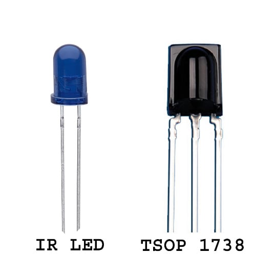
An IR LED is used to transmit data wirelessly in digital form (0 – LED OFF or 1 – LED ON).
An IR photodiode or IR phototransistor receives this data. The IR photodiode or IR phototransistor gives different current values according to the intensity of light.
As transmitted data is in digital form (LED ON or OFF), a microcontroller can be used to decode this data.
It is possible to modulate the data transmitted and there are special decoder IR receivers available that can receive the modulated data.
For more information about IR communication, refer to the topic IR Communication in the sensors and modules section.
IR Communication using ATmega16/32 Microcontroller
Let's build IR communication with IR LED and TSOP1738 by interfacing them with AVR ATmega16. In this example, we are going to interface the keypad at the transmitter end to transmit keys and display them at the receiver end.
IR LED Interfacing With ATmega16/32
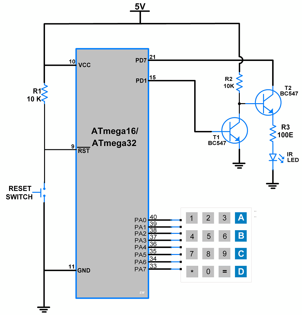
- Connect serial data pin PD1 (TXD) to the base terminal of transistor T1, and 38kHz frequency generated at pin PD7 connected to the collector terminal of transistor T2.
- Here transistor T1 is acting as an inverter and transistor T2 is acting as a switch. The output of transistor T2 is serial data modulating at 38kH as shown in the figure.
- IR LED connected in series with a 100-ohm resistor to the emitter terminal of transistor T2.
TSOP1738 Interfacing With ATmega16/32
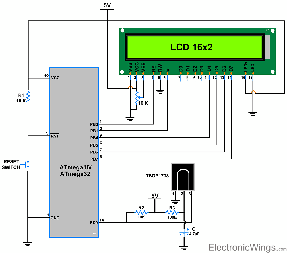
- Connect LCD 16x2 display at PORTB as shown in the figure above.
- Connect TSOP1738 to the (RXD) PD0 pin of PORTD as per other peripheral of the above connection.
Programming of IR Communication
Transmitter
Steps
- Attach Keypad.h and USART_RS232_H_file.h library.
- Generate 38kHz frequency using timer interrupt at PD7 pin.
- Using the keyboard find which key is pressed and assign the data using a switch case, for that key to transmit over serially.
- Here we first send the special character ‘$’.
- Then send the actual data, and then send the invert of actual data.
IR Transmitter Code for Atmega16
/*
 * IR_Serial_Tranasmitter.c
 *
 * http://www.electronicwings.com
 */


#define F_CPU 8000000UL
#include <avr/io.h>
#include <avr/interrupt.h>
#include <util/delay.h>
#include "USART_RS232_H_file.h"
#include "Keypad.h"
char g=0;

ISR(TIMER0_OVF_vect)
{
	g = ~g;
	if (g!=0)
	PORTD |= (1<<7);
	if (g==0)
	PORTD &= ~(1<<7);
	TCNT0 = 0xF4;
}

void Timer_dalay()
{
	TIMSK=(1<<TOIE0);	/* Enable timer interrupt */
	TCNT0 = 0xF4;		/* load TCNT0, count for 13us */
	TCCR0 = (1<<CS01);	/* Timer0, normal mode, /8 prescalar */
}

int main(void)
{
	DDRD |= 0xFF;		/* set PORTD as output port */
	USART_Init(1200);	/* set baud rate 1200 */
	sei();			/* enable global interrupt */
	Timer_dalay();		/* call timer function */
	char j,d=0;

	while(1)
	{
		j = keyfind();	/* search and find which key is pressed */
		switch (j)
		{
		case ('1'):
			USART_TxChar('$');	/* send the special character '$' */
			USART_TxChar('1');	/* send '1' */
			d = ~j;
			USART_TxChar(d);	/* send invert of '1' */
			_delay_ms(10);
			break;

		case ('2'):
			USART_TxChar('$');
			USART_TxChar('2');
			d = ~j;
			USART_TxChar(d);
			_delay_ms(10);
			break;

		case ('3'):
			USART_TxChar('$');
			USART_TxChar('3');
			d = ~j;
			USART_TxChar(d);
			_delay_ms(10);
			break;

		case ('4'):
			USART_TxChar('$');
			USART_TxChar('4');
			d = ~j;
			USART_TxChar(d);
			_delay_ms(10);
			break;

		case ('5'):
			USART_TxChar('$');
			USART_TxChar('5');
			d = ~j;
			USART_TxChar(d);
			_delay_ms(10);
			break;

		case ('6'):
			USART_TxChar('$');
			USART_TxChar('6');
			d = ~j;
			USART_TxChar(d);
			_delay_ms(10);
			break;

		case ('7'):
			USART_TxChar('$');
			USART_TxChar('7');
			d = ~j;
			USART_TxChar(d);
			_delay_ms(10);
			break;

		case ('8'):
			USART_TxChar('$');
			USART_TxChar('8');
			d = ~j;
			USART_TxChar(d);
			_delay_ms(10);
			break;

		case ('9'):
			USART_TxChar('$');
			USART_TxChar('9');
			d = ~j;
			USART_TxChar(d);
			_delay_ms(10);
			break;

		case ('0'):
			USART_TxChar('$');
			USART_TxChar('0');
			d = ~j;
			USART_TxChar(d);
			_delay_ms(10);
			break;

		case ('*'):
			USART_TxChar('$');
			USART_TxChar('*');
			d = ~j;
			USART_TxChar(d);
			_delay_ms(10);
			break;

		case ('#'):
			USART_TxChar('$');
			USART_TxChar('#');
			d = ~j;
			USART_TxChar(d);
			_delay_ms(10);
			break;
		}
	}
}
Receiver
Steps
- Attach LCD16x2_4bit.h and USART_Interrupt.h library from the given below.
- Here use the USART serial receive interrupt.
- When data received, check the first special character is ‘$’ if yes then counter increment by one.
- Then take the second data and third inverted data and store on two different variables.
- Here cross-check the data and invert data is received correctly or not by using logical operation (Here we use logical OR operation). If it is correct, then display the received data otherwise do not display.
IR Receiver Code for Atmega16
/*
 * IR_Serial_Receiver.c
 *
 * http://www.electronicwings.com
 */


#define F_CPU 8000000UL
#include <avr/io.h>
#include <avr/interrupt.h>
#include <util/delay.h>
#include "USART_Interrupt.h"
#include "LCD16x2_4bit.h"
char check,data,invdata,count=0;

ISR(USART_RXC_vect)
{
	if(count == 0)
	{
		if (USART_RxChar() == '$')/* Check special character '$' */
		count++;		/* If yes, increment count by 1 */

		else			/* Else count set to 0 */
		count=0;
	}

	if (count == 1)
	{
		data = USART_RxChar();	/* Second character is data */
		count++;		/* Count increment by one */
	}

	if (count == 2)
	{
		invdata = USART_RxChar();/* Third character is inverse data */
		if ((data | invdata)==0xFF)/* If data OR inverse data is 0xFF */
		{
			lcd_gotoxy(0,0);/* Set the column and row */
			lcddata(data);	/* Display the data on LCD */
		}
	count=0;			/* Count set to zero */
	}
}

int main(void)
{
	lcdinit();		/* Initialize the 16x2 LCD */
	USART_Init(1200);	/* Set baud rate 1200 */
	lcd_clear();		/* Clear the LCD */
	sei();			/* Enable the global interrupt */
    	while(1);
}
Video of IR Communication using AVR ATmega16 Controller
Components Used |
||
|---|---|---|
| ATmega 16 ATmega 16 |
X 1 | |
| Atmega32 Atmega32 |
X 1 | |
| BC547 TRANSISTORS BC547 TRANSISTORS |
X 4 | |
| 4x4 Matrix Keypad 4x4 Matrix Keypad |
X 1 | |
| LCD16x2 Display LCD16x2 Display |
X 1 | |
| Breadboard Breadboard |
X 2 | |
| IR LED Infrared Emitters IR LED Infrared Emitters |
X 1 | |
| TSOP1738 Infrared Receivers Infrared Receivers 38kHz IR Receiver |
X 1 | |