Introduction to PWM
Pulse Width Modulation (PWM) is a technique by which the width of a pulse is varied while keeping the frequency of the wave constant.

PWM Generation
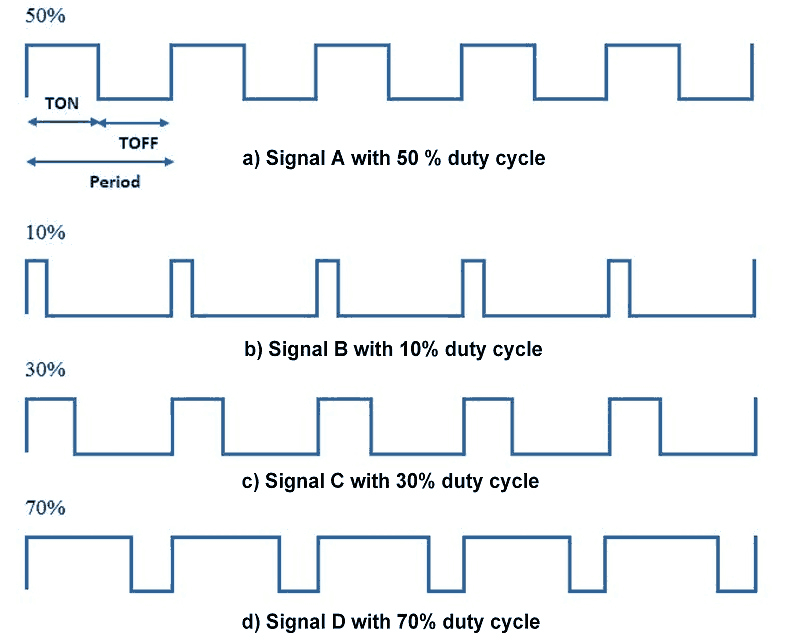
A period of a pulse consists of an ON cycle (VCC) and an OFF cycle (GND). The fraction for which the signal is ON over a period is known as a duty cycle.
E.g. A pulse with a period of 10ms will remain ON (high) for 2ms.Therefore, the duty cycle will be
D = 2ms / 10ms = 20%
Through the PWM technique, we can control the power delivered to the load by using the ON-OFF signal. The PWM signals can be used to control the speed of DC motors and to change the intensity of the LED. Moreover, it can also be used to generate sine signals. Pulse Width Modulated signals with different duty cycle are shown below.
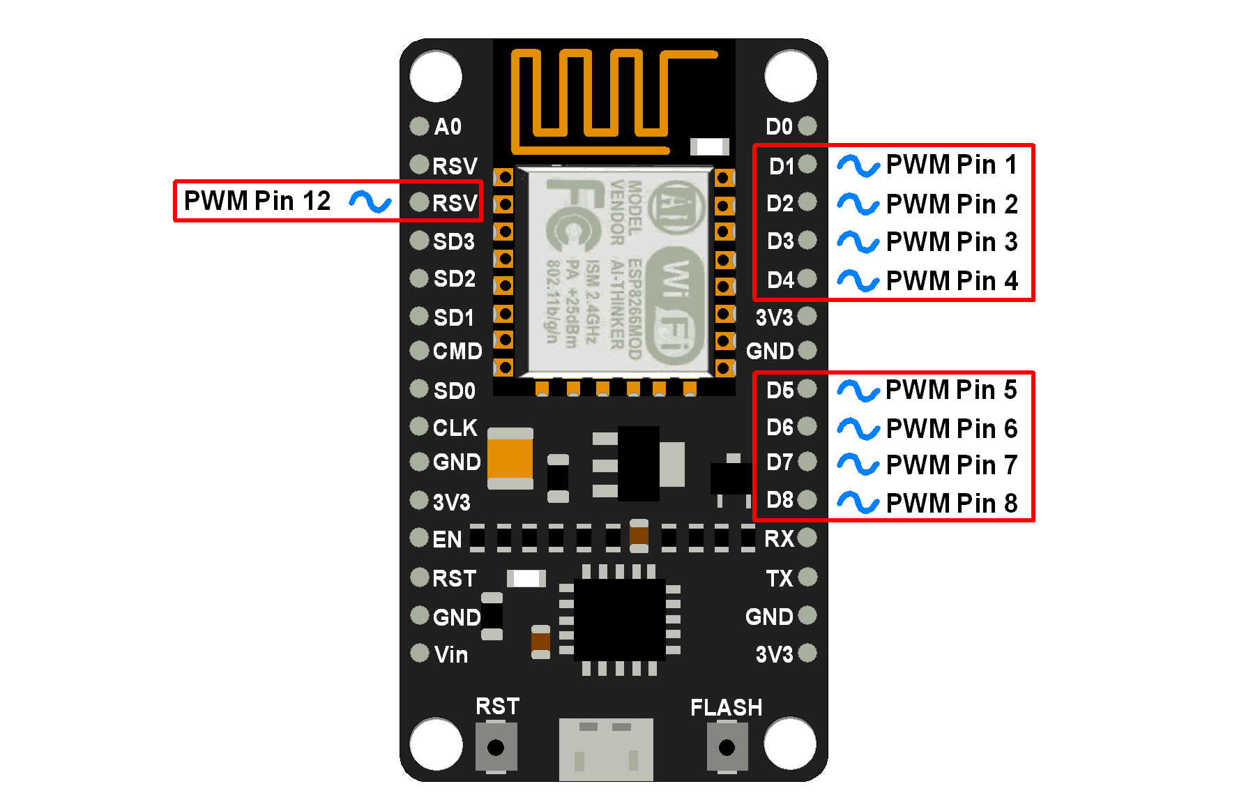
NodeMCU based ESP8266 has the functionality of PWM interfaces via software programming. It is achieved with the timer interruption method. The PWM frequency range for ESP8266 is adjustable up to 1KHz.
NodeMCU PWM Pins
Arduino function for NodeMCU PWM
analogWrite(pin, dutycycle): Enables software PWM on the specified pin. duty cycle is in the range from 0 to PWMRANGE, i.e. 1023 by default.
analogWrite(pin, 0): Disables PWM on the specified pin.
analogWriteRange(new_range): This function is used to change the PWM range (duty cycle).
analogWriteFreq(new_frequency): PWM frequency is 1kHz by default. Call this function to change it with new frequency.PWM frequency is in the range of 1 – 1000Khz.
Example
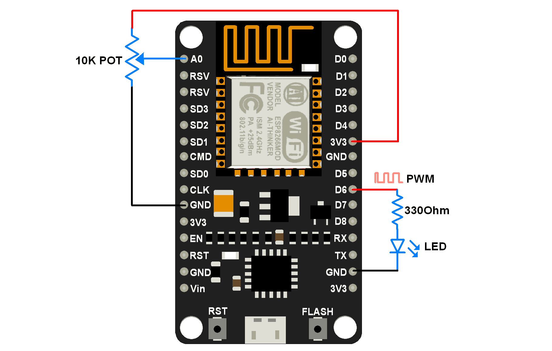
Let’s write an Arduino sketch to set PWM on 6thpin of NodeMCU and vary its duty cycle with the potentiometer connected to the ADC pin of NodeMCU. Here we connect LED on PWM pin to visualize the effect (Brightness of LED) of PWM variation.
Interfacing Diagram
NodeMCU PWM Code using Arduino IDE
uint8_t LEDpin = D6;

/* By default PWM frequency is 1000Hz and we are using same
   for this application hence no need to set */

void setup(){
  Serial.begin(9600);
  analogWrite(LEDpin, 512);  /* set initial 50% duty cycle */
}

void loop(){
  uint16_t dutycycle =  analogRead(A0); /* read continuous POT and set PWM duty cycle according */
  if(dutycycle > 1023) dutycycle = 1023;/* limit dutycycle to 1023 if POT read cross it */
  Serial.print("Duty Cycle: ");  Serial.println(dutycycle);
  analogWrite(LEDpin, dutycycle);
  delay(100);
}
Components Used |
||
|---|---|---|
| NodeMCU NodeMCUNodeMCU |
X 1 | |
| ESP12F ESP12E |
X 1 | |