MBED is a platform which is developed by ARM and is based on the NXP LPC1768 microcontroller, with an online compiler and a software library.
MBED is most popular platform which is developed by ARM, which is have its own online compiler with many libraries.

Features of ARM MBED:
- 32-bit ARM Cortex-M3 hardware
- Drag-and-drop programming, with the board represented as a USB drive
- 32kB on chip SRAM
- 512kB on chip Flash program memory
- 100MHz high speed operation
Easy to use online compile
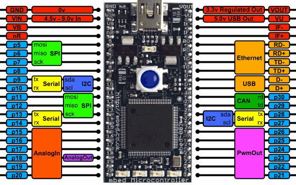
ARM MBED Pin Diagram

The MBED platform which is based on the NXP LPC1768 developed by ARM, it’s operates on 32-bit ARM Cortex-M3 at 96MHz clock frequency.
The above diagram shows complete pinout diagram of ARM MBED board, which is commonly used for interface and their locations. Note that all the numbered pins (p5-p30) can also be used as DigitalIn (Digital Input) and DigitalOut (Digital Output) interfaces.
Vin - +5 Volt, 100mA External Power supply to the mbed board also external circuits powered through the Microcontroller
Vb - Battery backup input for Real Time Clock 1.8v-3.3v, 30uA
nR - Active-low reset pin with identical functionality to the reset button. Pull up resistor is on the board, so it can be driven with an open collector
IF+/- - Reserved for Future use
It has lots of interfaces like Ethernet, USB Host and Device, CAN, SPI, I2C, ADC, DAC, PWM and other I/O interfaces.
USB
- USB 2.0 full-speed device/Host/OTG controller with dedicated DMA controller and on-chip PHY for device, Host, and OTG functions.
UART
- It has 3 UART (Universal Asynchronous Receiver Transmitter) interfaces.
- UART is used for serial communication devices that support UART communication. It uses 2 wires Rx and Tx for communication.
- Many of the electronic devices like GSM, GPS, Bluetooth etc. Use UART communication at different baud rates like 9600, 14400, 19200 etc.
SPI
- SPI is a serial communication protocol that uses 4 wires (MOSI-Master Out Slave In, MISO-Master In Slave Out, SCK-Serial Clock, SS-Slave Select) for communication between devices that support this protocol.
- It has 2 SPI (Serial Peripheral Interface) interfaces, SPI0 and SPI1.
- Many digital displays, ADC chips, SD cards support SPI protocol.
I2C
- I2C is a 2-wire serial communication protocol. It uses 2 wires, SDA-Serial Data and SCL-Serial Clock.
- It has two I2C (Inter Integrated Circuit) interfaces, I2C0 and I2C1.
- It is used for communication with I2C devices like magnetometer, gyroscope etc.
Timer
- It has four 32-bit Timers, Timer0 – Timer4.
- These timers are used for generating precise delays, input capture, and waveform generation.
PWM
- It has up to 6 PWM outputs on-board.
- It can generate 6 single edge controlled or 3 double edged controlled PWMs.
- PWMs are used for controlling speed of motors.
RTC
- It has an inbuilt RTC.
- It can be programmed to maintain a clock and calendar.
- It has various counter registers that keep count of clock ticks to maintain the current time and date.
- It also has alarm functionality. Separate alarm registers are provided for it.
ADC
- It has on-board six channel 12-bit ADCs (AD0 – AD5) that provide the capability to process analog signals.
- Analog signals from sensors like Temperature, Humidity etc. Can be read using ADC.
DAC
- It has an inbuilt 10-bit DAC.
- It can be used to generate analog signals which are useful for certain audio and video applications.
Components Used |
||
|---|---|---|
| ARM mbed 1768 LPC1768 Board ARM mbed 1768 Board |
X 1 | |
