Introduction to 8051 Timers
8051 microcontrollers have two timers and counters which work on the clock frequency. Timer/counter can be used for time delay generation, counting external events, etc.
8051 Clock
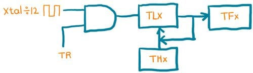
Every Timer needs a clock to work, and 8051 provides it from an external crystal which is the main clock source for Timer. The internal circuitry in the 8051 microcontrollers provides a clock source to the timers which is 1/12th of the frequency of crystal attached to the microcontroller, also called Machine cycle frequency.

For example, suppose we have a crystal frequency of 11.0592 MHz then the microcontroller will provide 1/12th i.e.
Timer clock frequency= (Xtal Osc.frequency)/12 = (11.0592 MHz)/12 = 921.6 KHz
period T= 1/(921.6 kHz)=1.085 μS
8051 Timer
8051 has two timers Timer0 (T0) and Timer1 (T1), both are 16-bit wide. Since 8051 has 8-bit architecture, each of these is accessed by two separate 8-bit registers as shown in the figure below. These registers are used to load timer count.

8051 has a Timer Mode Register and Timer Control Register for selecting a mode of operation and controlling purpose.
Let's see these registers,
TMOD register
TMOD is an 8-bit register used to set timer mode of timer0 and timer1.

Its lower 4 bits are used for Timer0 and the upper 4 bits are used for Timer1
Bit 7,3 – GATE:
1 = Enable Timer/Counter only when the INT0/INT1 pin is high and TR0/TR1 is set.
0 = Enable Timer/Counter when TR0/TR1 is set.
Bit 6,2 - C/(Counter/Timer): Timer or Counter select bit
1 = Use as Counter
0 = Use as Timer
Bit 5:4 & 1:0 - M1:M0: Timer/Counter mode select bit
These are Timer/Counter mode select bit as per the below table
| M1 | M0 | Mode | Operation |
|---|---|---|---|
| 0 | 0 | 0 (13-bit timer mode) | 13-bit timer/counter, 8-bit of THx & 5-bit of TLx |
| 0 | 1 | 1 (16-bit timer mode) | 16-bit timer/counter, THx cascaded with TLx |
| 1 | 0 | 2 (8-bit auto-reload mode) | 8-bit timer/counter (auto-reload mode), TLx reload with the value held by THx each time TLx overflow |
| 1 | 1 | 3 (split timer mode) | Split the 16-bit timer into two 8-bit timers i.e. THx and TLx like two 8-bit timer |
TCON Register

TCON is an 8-bit control register and contains a timer and interrupt flags.
Bit 7 - TF1: Timer1 Overflow Flag
1 = Timer1 overflow occurred (i.e. Timer1 goes to its max and roll over back to zero).
0 = Timer1 overflow not occurred.
It is cleared through software. In the Timer1 overflow interrupt service routine, this bit will get cleared automatically while exiting from ISR.
Bit 6 - TR1: Timer1 Run Control Bit
1 = Timer1 start.
0 = Timer1 stop.
It is set and cleared by software.
Bit 5 – TF0: Timer0 Overflow Flag
1 = Timer0 overflow occurred (i.e. Timer0 goes to its max and roll over back to zero).
0 = Timer0 overflow not occurred.
It is cleared through software. In the Timer0 overflow interrupt service routine, this bit will get cleared automatically while exiting from ISR.
Bit 4 – TR0: Timer0 Run Control Bit
1 = Timer0 start.
0 = Timer0 stop.
It is set and cleared by software.
Bit 3 - IE1: External Interrupt1 Edge Flag
1 = External interrupt1 occurred.
0 = External interrupt1 Processed.
It is set and cleared by hardware.
Bit 2 - IT1: External Interrupt1 Trigger Type Select Bit
1 = Interrupt occurs on falling edge at INT1 pin.
0 = Interrupt occur on a low level at the INT1 pin.
Bit 1 – IE0: External Interrupt0 Edge Flag
1 = External interrupt0 occurred.
0 = External interrupt0 Processed.
It is set and cleared by hardware.
Bit 0 – IT0: External Interrupt0 Trigger Type Select Bit
1 = Interrupt occurs on falling edge at INT0 pin.
0 = Interrupt occur on a low level at INT0 pin.
Let's see the timers modes
8051 Timer Modes
Timers have their operation modes which are selected in the TMOD register using M0 & M1 bit combinations.
Mode 0 (13-bit timer mode)
Mode 0 is a 13-bit timer mode for which 8-bit of THx and 5-bit of TLx (as Prescaler) are used. It is mostly used for interfacing possible with old MCS-48 family microcontrollers.

As shown in the above figure, 8-bit of THx and lower 5-bit of TLx used to form a total 13-bit timer. Higher 3-bits of TLx should be written as zero while using timer mode0, or it will affect the result.
Example
Let's generate a square wave of 2mSec period using an AT89C51 microcontroller with timer0 in mode0 on the P1.0 pin of port1. Assume xtal oscillator frequency of 11.0592 MHz.

As the Xtal oscillator frequency is 11.0592 MHz we have a machine cycle of 1.085uSec. Hence, the required count to generate a delay of 1mSec. is,
Count =(1×10^-3)/(1.085×10^-6) ≈ 921
The maximum count of Mode0 is 2^13 (0 - 8191) and the Timer0 count will increment from 0 – 8191. So we need to load value which is 921 less from its maximum count i.e. 8191. Also, here in the below program, we need an additional 13 MC (machine cycles) from call to return of delay function. Hence value needed to be loaded is,
Value=(8191-Count)+Function_MCycles+1 =7284= 0x1C74
So we need to load 0x1C74 value in Timer0.
1C74 = 0001 1100 0111 0100 b, now load lower 5-bit in TL0 and next 8-bit in TH0
so here we get,
TL0 = 0001 0100 = 0x14 and TH0 = 1110 0011 = 0xE3
Programming steps for delay function
- Load Tmod register value i.e. TMOD = 0x00 for Timer0/1 mode0 (13-bit timer mode).
- Load calculated THx value i.e. here TH0 = 0xE3.
- Load calculated TLx value i.e. here TL0 = 0x14.
- Start the timer by setting a TRx bit. i.e. here TR0 = 1.
- Poll TFx flag till it does not get set.
- Stop the timer by clearing TRx bit. i.e. here TR0 = 0.
- Clear timer flag TFx bit i.e. here TF0 = 0.
- Repeat from step 1 to 7 for the delay again.
8051 timer mode0 code
/*
 * 8051_Timer_Mode0
 * http://www.electronicwings.com
 */
#include <reg51.h>			/* Include x51 header file */
sbit test = P1^0;			/* set test pin 0 of port1 */

void timer_delay()			/* Timer0 delay function */
{
	TH0 = 0xE3;			/* Load 8-bit in TH0 (here Timer0 used) */
	TL0 = 0x14;			/* Load 5-bit in TL0 */
	TR0 = 1;			/* Start timer0 */
	while(TF0 == 0);		/* Wait until timer0 flag set */
	TR0 = 0;			/* Stop timer0 */
	TF0 = 0;			/* Clear timer0 flag */
}
void main()
{
	TMOD = 0x00;			/* Timer0/1 mode0 (13-bit timer mode) */
	while(1)
	{
		test = ~test;		/* Toggle test pin */
		timer_delay();		/* Call timer0 delay */
	}
}
Mode1 (16-bit timer mode)
Mode 1 is a 16-bit timer mode used to generate a delay, it uses 8-bit of THx and 8-bit of TLx to form a total 16-bit register.

Example
Let’s generate a square wave of 2mSec time period using an AT89C51 microcontroller with timer0 in mode1 on the P1.0 pin of port1. Assume Xtal oscillator frequency of 11.0592 MHz.
As Xtal is 11.0592 MHz we have a machine cycle of 1.085uSec.
Hence, the required count to generate a delay of 1mSec. is,
Count =(1×10^(-3)) / (1.085×10^(-6) ) ≈ 921
And mode1 has a max count is 2^16 (0 - 65535) and it increments from 0 to 65535 so we need to load value which is 921 less from its max. count i.e. 65535. Also, here in the below program, we need an additional 13 MC (machine cycles) from call to return of delay function. Hence value needed to be loaded is,
Value=(65535-Count)+Function_MCycles+1 =64615= (FC74)Hex
So we need to load FC74 Hex value higher byte in TH0 and lower byte in TL0 as,
TH0 = 0xFC & TL0 = 0x74
Programming steps for delay function
- Load Tmod register value i.e. TMOD = 0x01 for Timer0 mode1 (16-bit timer mode).
- Load calculated THx value i.e. here TH0 = 0xFC.
- Load calculated TLx value i.e. here TL0 = 0x74.
- Start the timer by setting a TRx bit. i.e. here TR0 = 1.
- Poll TFx flag till it does not get set.
- Stop the timer by clearing TRx bit. i.e. here TR0 = 0.
- Clear timer flag TFx bit i.e. here TF0 = 0.
- Repeat from step 1 to 7 for the delay again.
8051 timer mode1 code
/*
 * 8051_Timer_Mode1
 * http://www.electronicwings.com
 */
#include <reg51.h>		/* Include x51 header file */
sbit test = P1^0;		/* set test pin0 of port1 */

void timer_delay()		/* Timer0 delay function */
{
	TH0 = 0xFC;		/* Load higher 8-bit in TH0 */
	TL0 = 0x74;		/* Load lower 8-bit in TL0 */
	TR0 = 1;		/* Start timer0 */
	while(TF0 == 0);	/* Wait until timer0 flag set */
	TR0 = 0;		/* Stop timer0 */
	TF0 = 0;		/* Clear timer0 flag */
}
void main()
{
	TMOD = 0x01;		/* Timer0 mode1 (16-bit timer mode) */
	while(1)
	{
		test = ~test;	/* Toggle test pin */
		timer_delay();	/* Call timer0 delay */
	}
}
Mode2 (8-bit auto-reload timer mode)
in 8051 mcu mode 2 is an 8-bit auto-reload timer mode. In this mode, we have to load the THx-8 bit value only. when the Timer gets started, the THx value gets automatically loaded into the TLx and TLx starts counting from that value. After the value of TLx overflows from the 0xFF to 0x0, the TFx flag gets set and again value from the THx gets automatically loaded into the TLx register. That’s why this is called the auto-reload mode.
Example
Here we are generating a square wave on PORT1.0 with 200uSec. time period using Timer1 in mode2. We will use 11.0592 MHz Xtal oscillator frequency.
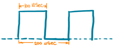
As Xtal is 11.0592 MHz we have a machine cycle of 1.085uSec. Hence, the required count to generate a delay of 1mSec. is,
Count =(100×10^(-6)) / (1.085×10^(-6) )≈92
And mode2 has a max count is 2^8 (0 - 255) and it increment from 0 – 255 so we need to load value which is 92 less from its max. count i.e. 255. Hence value need to be load is,
Value=(255-Count)+1 =164= 0xA4
So we need to load A4 Hex value in a higher byte as,
TH1 = 0xA4
Programming steps for delay function in 8051 MCU
- Load Tmod register value i.e. TMOD = 0x20 for Timer1 mode2 (8-bit timer auto reload mode).
- Load calculated THx value i.e. here TH1 = 0xA4.
- Load same value for TLx i.e. here TL1 = 0xA4.
- Start the timer by setting a TRx bit. i.e. here TR1 = 1.
- Poll TFx flag till it does not get set.
- Clear timer flag TFx bit i.e. here TF1 = 0.
- Repeat from step 5 and 6 for the delay again.
8051 timer mode2 code
/*
 * 8051_Timer_Mode2
 * http://www.electronicwings.com
 */
#include <reg51.h>			/* Include x51 header file */
sbit test = P1^0;			/* set test pin0 of port1 */

void main()
{
	TMOD = 0x20;			/* Timer1 mode2 (8-bit auto reload timer mode) */
	TH1 = 0xA4;			/* Load 8-bit in TH1 */
	TL1 = 0xA4;			/* Load 8-bit in TL1 once */
	TR1 = 1;			/* Start timer1 */
	while(1)
	{
		test = ~test;		/* Toggle test pin */
		while(TF1 == 0);	/* Wait until timer1 flag set */
		TF1 = 0;		/* Clear timer1 flag */
	}
}
Timer interrupt in 8051 Microcontroller
8051 has two timer interrupts assigned with different vector address. When Timer count rolls over from its max value to 0, it sets the timer flag TFx. This will interrupt the 8051 microcontroller to serve ISR (interrupt service routine) if global and timer interrupt is enabled.
| Interrupt source | Vector address |
|---|---|
| Timer 0 overflow (TF0) | 000BH |
| Timer 1 overflow (TF1) | 001BH |
The timer overflow interrupt assigned with the vector address shown in the table. 8051 microcontroller jumps directly to the vector address on the occurrence of a corresponding interrupt.

Example
Here we will generate a square wave of 10Hz on PORT1.0 using Timer0 interrupt. We will use Timer0 in mode1 with 11.0592 MHz oscillator frequency.

As Xtal is 11.0592 MHz we have a machine cycle of 1.085uSec. Hence, the required count to generate a delay of 50mSec. is,
Count =(50×10^(-3)) / (1.085×10^(-6) ) ≈ 46080
And mode1 has a max count is 2^16 (0 - 65535) and it increment from 0 – 65535 so we need to load value which is 46080 less from its max. count i.e. 65535. Hence value need to be load is,
Value=(65535-Count)+1 =19456= (4C00)Hex
So we need to load 4C00 Hex value in a higher byte and lower byte as,
TH0 = 0x4C & TL0 = 0x00
Note that the TF0 flag no need to clear by software as a microcontroller clears it after completing the ISR routine.
8051 timer interrupt code
/*
 * 8051_Timer_Interrupt
 * http://www.electronicwings.com
 */
#include<reg51.h>		/* Include x51 header file */
sbit test = P1^0;		/* set test pin0 of port1 */

void Timer_init()
{
	TMOD = 0x01;		/* Timer0 mode1 */
	TH0 = 0x4C;		/* 50ms timer value */
	TL0 = 0x00;
	TR0 = 1;  	      	/* Start timer0 */
}


void Timer0_ISR() interrupt 1	/* Timer0 interrupt service routine (ISR) */
{
	test = ~test;  		/* Toggle port pin */
	TH0 = 0x4C;      	/* 50ms timer value */
	TL0 = 0x00;
}

int main(void)
{
	EA  = 1;         	/* Enable global interrupt */
	ET0 = 1;         	/* Enable timer0 interrupt */
	Timer_init();
  	while(1);
}
Video
Components Used |
||
|---|---|---|
| 8051 AT89c51 8051 AT89c51 |
X 1 | |