8051 Microcontroller
Microcontroller consists of all features that are found in microprocessors with additional built-in ROM, RAM, I/O ports, Serial ports, Timers, Interrupts, and Clock circuits. It is an entire computer on a single chip that is embedded within applications. Microcontrollers are widely used in many domestic (washing machines, VCD players, microwave oven, robotics, etc.) as well as industrial and automobile areas.
The 8051 is the first microcontroller of the MCS-51 family developed by Intel Corporation in 1980. It was developed using N-type Metal-Oxide-Semiconductor (NMOS) technology and later it came to be identified by a letter C in their names e.g. 80C51 which was developed with Complementary Metal-Oxide-Semiconductor (CMOS) technology which consumes less power than NMOS and made it better compatible for battery-powered applications.
Microcontrollers can be classified on the basis of their bit processing capability e.g. 8-bit microcontroller means it can read, write, and process 8-bit data. Basically, it specifies the size of the data bus. Today microcontrollers are designed with much more compact, cheap, and powerful specifications like AVR and PIC.
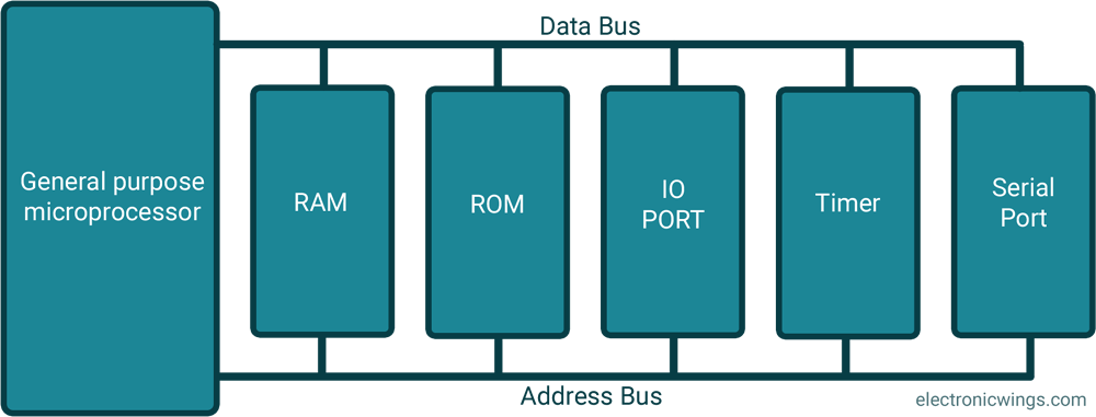
As shown in the figure, Microprocessors need external devices such as RAM for data storage, ROM for program storage, PPI 8255 for I/O port, 8253 for timer, and USART for serial communication.
All these peripherals are integrated together to form a controlling unit ready to embed within applications.

Whereas the microcontroller has all memories and ports available on-chip as shown in the figure. This makes microcontrollers the most popular. Later many semiconductor companies developed their own microcontrollers with different specifications.
8051 Microcontroller Family Member Specifications
Find below, the specifications for various popular 8051 family members developed by mentioned semiconductor companies.
| Developed by | Family members | RAM(bytes) | ROM(Kbytes) | Timers | I/O pins | Serial port | Interrupt sources |
|---|---|---|---|---|---|---|---|
| Intel | 8051 | 128 | 4 | 2 | 32 | 1 | 6 |
| 8052 | 256 | 8 | 3 | 32 | 1 | 8 | |
| 8031 | 128 | None | 2 | 32 | 1 | 6 | |
| Atmel | AT89C51 | 128 | 4 | 2 | 32 | 1 | 6 |
| AT89C52 | 256 | 8 | 3 | 32 | 1 | 6 | |
| Dallas | DS5000-8 | 128 | 8 | 2 | 32 | 1 | 6 |
| DS5000-32 | 128 | 32 | 2 | 32 | 1 | 6 | |
| Philips | P89C51RD2 | 1024 | 64 | 3 | 32 | 1 | 8 |
Pin Diagram of 8051 Microcontroller

Architecture of 8051 Microcontroller
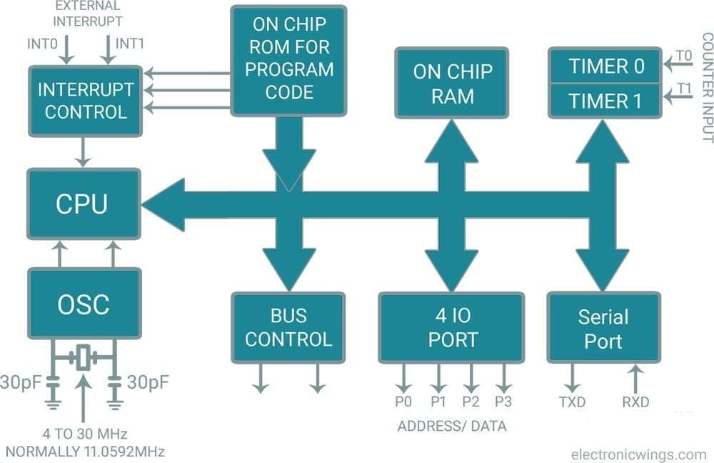
All 8051 microcontrollers have unique architecture as shown in the figure, which consists of functional blocks to build 8051 powerful controlling machines.
CPU
Microcontroller 8051 has a central processing unit which is also called ALU (Arithmetic Logic Unit) which performs all arithmetic and logical operation.
RAM (Random-access memory)
- Microcontroller 8051 has 128-byte RAM for data storage.
- It is a Volatile type of memory. That means the data is lost when power to the device is turned off.
- It is used during execution time to store data temporarily.
- RAM consists of a register bank, stack, and temporary data storage with some special function registers (SFR’s).
ROM (Read Only Memory)
- In 8051, 4KB ROM is available for program storage.
- It is a Non-Volatile type of memory. It means that data is not lost even in the event of power failure.
- 8051 has a 16-bit address. It means it can access 2^16 memory locations and we can interface up to 64 KB of program memory externally in case of large applications.
Sizes specified of RAM and ROM are different by their manufacturer.
8051 Timers and Counters
- Microcontroller 8051 has two timer pins T0 and T1
- By these timers, we can generate a delay of a particular time in timer mode
- We can count external pulses or events in counter mode
- Two 16-bit timer registers are available as T0 (TH0 & TL0) and T1 (TH1 & TL1), e.g. If we want to load T0 then we can load Higher 8-bit in TH0 & Lower 8-bit in TL0
- TMOD and TCON registers are used to select mode and control the timer operation
8051 Interrupts
- Interrupts are requested by internal or external peripherals which are masked while unused.
- Interrupt handler routines are called after each interrupts event occurs.
- These routines are called an Interrupt Service Routine (ISR) and are located in special memory loc.
- INT0 and INT1 pins used to accept external interrupts.
Oscillator
- it is used to provide a clock to the 8051 which decides the speed and baud rate.
- We use crystals of frequency varying from 4MHz to 30 MHz. Normally we use 11.0592 MHz frequency which is required for a 9600 baud rate in serial communication.
8051 I/O Ports
- 8051 Microcontroller has four Input/output ports P0, P1, P2, P3
- Each port is 8-bit wide and their SFR (P0, P1, P2, P3) are bit accessible i.e. we can set or reset individual bits.
- Some ports have dual functionality on their pins as,
- P0 I/O pins are multiplexed with an 8-bit data bus and lower order address bus (AD0-AD7) which are de-multiplexed by ALE signal and latch used in external memory access operation.
- P2 I/O pins are multiplexed with the remaining higher order address bus (A8-A15)
- P3 I/O pins also have dual functions as,
- P3.0 – RXD – Serial data receive.
- P3.1 – TXD – Serial data transmit.
- P3.2 – INT0 – External Interrupt 0.
- P3.3 – INT1 – External Interrupt 1.
- P3.4 – T0 – Clock input for counter 0.
- P3.5 – T1 – Clock input for counter 1.
- P3.6 – WR – Signal for writing to external memory.
- P3.7 – RD – Signal for reading from external memory.
- P0 and P2 can’t be used as I/O pins in the external memory access operation
8051 Serial Communication port
- 8051 MCU has two serial communication (UART) pins TXD and RXD used for transmitting and receive data serially via the SBUF register
- SCON SFR used to control serial operation
Components Used |
||
|---|---|---|
| 8051 AT89c51 8051 AT89c51 |
X 1 | |