Description

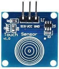
- The sensor consists of the TTP223 IC which is based on the capacitive sensing principle. It consists of a sensing electrode and an oscillator circuit.
- When a conductive material that is finger comes in contact with the sensing electrode, it changes the capacitance of the electrode.
- This change is detected by the oscillator circuit, then the oscillator circuit generates a digital output signal.
- This indicates the touch or proximity of the object. It is widely used in various electronic devices such as toys and touch switches.
Specifications of Touch Sensor
- The power supply for the sensor is 2 to 5.5V DC.
- It has a response time in the touch mode is 60mS and in the low power mode of about 220mS.
- Output high VOH is 0.8V VCC.
- Output low VOL is 0.3V VCC.
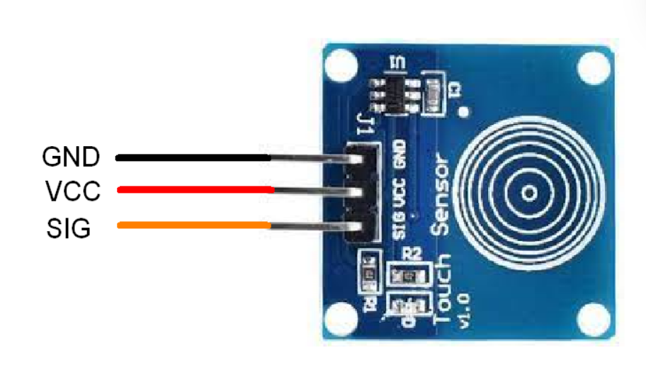
Pinouts of Touch Sensor v1.0

- VCC: Power supply pin
- SIG: This is the signal output pin. It provides a digital output signal when a touch is detected on the sensor.
- GND: Connected to the ground.
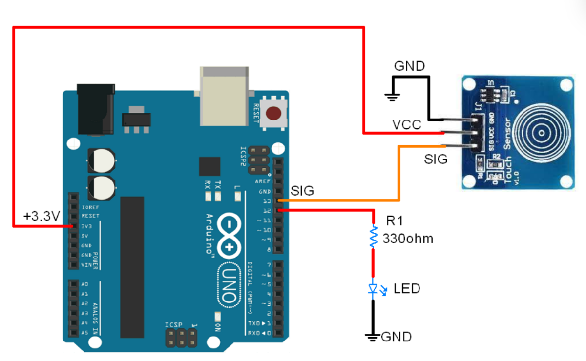
TTP223 Touch Sensor Interfacing with Arduino to control a LED

Toggle the LED using Touch Sensor and Arduino
As you touch the finger to the sensor, the sensor will detect it and make the ledpin HIGH which will turn ON the led.
On the other hand, as we remove the finger from the sensor, again the sensor will detect it and make the ledpin LOW which will turn OFF the LED.
This was the basic logic behind the code.
Here we have used the same logic in the code below
Code for Toggling the LED using Touch Sensor and Arduino
#define sensor_pin 13
#define led_pin 12

int laststate = LOW;
int currentstate ;
int ledstate = LOW;

void setup() {
  Serial.begin(115200);
  pinMode(sensor_pin,INPUT);
  pinMode(led_pin,OUTPUT);
}

void loop() {
  int currentstate = digitalRead(sensor_pin);
  if(laststate == LOW && currentstate == HIGH){
    if(ledstate == LOW){
      ledstate = HIGH;
    }
    else if(ledstate == HIGH){
      ledstate = LOW;
    }
    digitalWrite(led_pin, ledstate);
  }
  laststate = currentstate;
}
- Now upload the code.
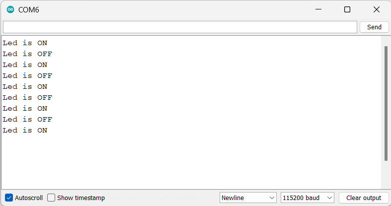
- After uploading the code open the serial monitor and set the baud rate to 15200 to see the output.
Output on the serial monitor

Let’s understand the code
In the code, first, we are defining the sensor pin and led pin as 13 and 12 respectively.
#define sensor_pin 13
#define led_pin 12
Then we will define the variables for storing the states of the sensor and led which are currentstate, laststate, and ledstate.
Initially, we will declare them as LOW.
int laststate = LOW;
int currentstate ;
int ledstate = LOW;
In setup function
We have initiated the serial communication with a 115200 Baud rate.
Serial.begin(115200);Then we set the pins as INPUT or OUTPUT using the function pinMode. We have set the sensor_pin as INPUT and led_pin as OUTPUT.
  pinMode(sensor_pin,INPUT);
  pinMode(led_pin,OUTPUT);
In loop function
We first, store the data of the sensor in the currentstate variable using the digitalRead function.
int currentstate = digitalRead(sensor_pin);The first if statement checks if the previous state of the input pin was LOW and the current state is HIGH. This condition indicates that a rising edge has occurred.
If a rising edge has occurred, we check the current state of the LED using the ledstate variable.
If the LED is currently off (LOW), the code sets the ledstate variable to HIGH to turn it on.
If the LED is currently on (HIGH), the code sets the ledstate variable to LOW to turn it off.
Finally, we write the new state of the LED to the output pin using the digitalWrite() function.
The ledstate variable is then updated to store the current state.
if(laststate == LOW && currentstate == HIGH){
    if(ledstate == LOW){
      ledstate = HIGH;
    }
    else if(ledstate == HIGH){
      ledstate = LOW;
    }
    digitalWrite(led_pin, ledstate);
  }
  laststate = currentstate;
Components Used |
||
|---|---|---|
| TTP223N 1 KEY TOUCH PAD DETECTOR IC TTP223N is a touch pad detector IC for 1 touch key. |
X 1 | |
| Arduino UNO Arduino UNO |
X 1 | |
Downloads |
||
|---|---|---|
|
|
Touch_Sensor_Arduino | Download |
