Introduction
Vehicle Collision
- A vehicle collision detection system is a system used to identify accident scenarios where the vehicle collides with another vehicle or some infrastructure element.
- By adding internet facility to the system, we can send this vehicle collision data to a cloud to create an IoT based system. An IoT based system provides real-time data that can be monitored remotely.
- Using Microsoft Azure services, we can add functionalities such as processing the collision data sent to Azure cloud and taking some predetermined action on it.
Here, we will create an IoT based application for vehicle collision detection using Microsoft Azure services.
- In this application, we will send vehicle collision data to an Azure IoT Hub. The Hub will send this data to a Web App, where the data will be displayed on a graph. The Web App can be accessed by any person who has the URL for the Web App. We will also process this vehicle collision data and send notifications via email to concerned people.
- The vehicle collision detection system we will be using makes use of accelerometer and gyroscope data from an MPU6050 to determine a collision and a simple logic determines a severity index for the collision. If the severity index is beyond a threshold, collision data is sent to an IoT Hub hosted by Microsoft Azure.
For this application, we will need the following :
1. A NodeMCU which can send data to an IoT Hub.
The code for the NodeMCU device is available in Source Code section at the end of this page.
Details about the code and how to set up the device are covered below in the later sections.
2. An MPU6050 that will provide us with the accelerometer and gyroscope data.
Refer MPU6050 Sensor Module in the Sensors and Modules section for information about MPU6050.
Refer MPU6050 Interfacing with NodeMCU in the NodeMCU interfaces section to know how MPU6050 is interfaced with a NodeMCU.
3. A Microsoft Azure account.
Refer Microsoft Azure Free Account Sign-Up in the Getting Started section of Microsoft Azure to create your free Microsoft Azure account if you do not already have one.
4. A Web App on Microsoft Azure that will be used for displaying the collision data.
The code for the Web App is provided in the Source Code section at the end of this page.
How to use this Web App and how to deploy it on Microsoft Azure is covered below in the later sections.
Let’s begin with the vehicle collision detection system.
Vehicle Collision Detection
The vehicle collision detection system consists of an MPU6050 interfaced with a NodeMCU.
The interfacing diagram for the same is shown below.
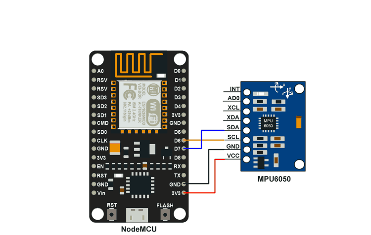
Interfacing MPU6050 Module With NodeMCU
Refer Sending DHT11 sensor data to IoT Hub using NodeMCU in the Getting Started section of Microsoft Azure to know how to send data to an IoT Hub. The basic steps covered in this document are necessary before you proceed further. Once you have set up the Arduino IDE for NodeMCU board, have installed the libraries mentioned in the document whose link is given above, you can proceed further.
The code we will be using for collision detection is available in the Source Code section at the end of this page.
Upload the code using the Arduino IDE to your NodeMCU device.
The code is a modification of the Sample application by Azure.
The logic and code snippet for the collision detection function used in the code is given below.
int coll_detect()
{
    int16_t AccelX_diff, GyroX_diff, GyroY_diff, GyroZ_diff;
    int16_t AccelX, AccelY, AccelZ, Temperature, GyroX, GyroY, GyroZ;
    Wire.beginTransmission(MPU6050SlaveAddress);
    Wire.write(MPU6050_REGISTER_ACCEL_XOUT_H);
    Wire.endTransmission();
    Wire.requestFrom(MPU6050SlaveAddress, (uint8_t)14);
    AccelX = (((int16_t)Wire.read()<<8) | Wire.read());
    AccelY = (((int16_t)Wire.read()<<8) | Wire.read());
    AccelZ = (((int16_t)Wire.read()<<8) | Wire.read());
    Temperature = (((int16_t)Wire.read()<<8) | Wire.read());
    GyroX = (((int16_t)Wire.read()<<8) | Wire.read());
    GyroY = (((int16_t)Wire.read()<<8) | Wire.read());
    GyroZ = (((int16_t)Wire.read()<<8) | Wire.read());

    if(check == 0)
    {
      AccelX_diff = 0;
      check = 1;
    }
    else
    {
      AccelX_diff = abs(AccelX - AccelX_prev);
      GyroX_diff = abs(GyroX - GyroX_prev);
      GyroY_diff = abs(GyroY - GyroY_prev);
      GyroZ_diff = abs(GyroZ - GyroZ_prev);
      if( (AccelX_diff > 8000) && ( (GyroX_diff > 300) || (GyroY_diff > 300) || (GyroZ_diff > 300) ) )
      {
        AccelX_diff = AccelX_diff/100 ;
      }
      else
      {
        AccelX_diff = 0;
      }

    }
    AccelX_prev = AccelX;
    GyroX_prev = GyroX;
    GyroY_prev = GyroY;
    GyroZ_prev = GyroZ;
    return AccelX_diff;
}
Collision Detection using MPU6050
1. Read the accelerometer and gyroscope values from MPU6050.
2. Calculate the difference between current and previous values of accelerometer and gyroscope.
3. If the difference in accelerometer values in X-direction, and gyroscope values in X, Y or Z directions are more than certain pre-determined thresholds (based on application requirements), then a collision is detected.
4. A collision severity index is calculated from this difference and is sent to the IoT Hub.
Note: This logic/algorithm is not the most optimum/accurate solution for collision detection. There are many ways in which you can design your collision detection system. You can use the algorithms already available or create your own.You can use this algorithm and fine tune it for your needs as well. Many of the algorithms are complex and involve the implementation of filters to give reliable results. There are many articles that can help you out with this. You can find information for this at these two links : Link1 (an instructable related to accelerometer and gyroscope use) and Link2 (application note on accelerometer and gyroscope by maxim integrated).
Now that our collision detection system is set up and is ready to send data to an IoT Hub, let’s set up the Microsoft Azure account to handle this data and process it according to our requirements.
You will have already set up your IoT Hub by now. If you have not, refer Creating an IoT Hub in Microsoft Azure in the Getting Started section of Microsoft Azure. Now we need to create a Web App and a Logic App for our application.
The Web App will host our web application which will display the collision information in a graph form.
The Logic App will process the data received by the IoT Hub and trigger an action that will send a notification mail to chosen recipients.
Web App
Refer Using Web Apps to visualize real time data from IoT Hub in the Getting Started section of Microsoft Azure.
Once you have created the Web App, you are ready to upload the web application to be hosted by the Web App. Follow the steps for uploading the web application as mentioned in the document.
There is only one thing you need to keep in mind, instead of downloading the web application from GitHub, download the application from the Source Code section at the end of this document. Then upload this web application using the method mentioned in the document.
The web application for vehicle collision detection will look as shown below.
Logic App
Refer Using Logic Apps for IoT remote monitoring and for sending notifications in the Getting Started section of Microsoft Azure.
Add a Service Bus and a Queue to it, and Add an Endpoint to your IoT Hub as mentioned in the document. In the step for adding a routing rule, follow the steps given with a minor modification. In the Query String, type collisionAlert = “true” in place of temperatureAlert = “true”.
Now we need to do add an additional routing path, a hot path so that the data received by the IoT Hub can be utilised by both, the Web App as well as the Logic App.Follow the same steps as given for Adding Route for Routing Data in the above document. Only difference is, in step 3, while selecting the Endpoint, select events as the endpoint. events is the default built-in endpoint. Also, enter true as the query string.
Create and configure a Logic App as mentioned in the document. Just change the subject and body of the email to something like Collision Alert ! or Severe Collision.
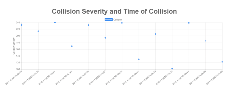
Our application is now completely set up and ready to be tested. Power the NodeMCU connected to the MPU6050 and start causing some collisions. Open the Web App, you will see the graph getting updated every time a collision event is detected. The recipients whose email Ids you entered while creating the Logic App will also get email alerts corresponding to the collision events. It may take a couple of minutes for the Logic App to receive the trigger event and for the recipients to receive emails. It may happen that you see the collision event immediately on the Web App but receive the notification mail 4-5 minutes later.
You can fine-tune the values for collision detection by taking into account the acceleration and deceleration values in your application and modifying the threshold values in the code you uploaded into the NodeMCU.
You can change the values from two files in the application code uploaded to the NodeMCU. The application code has 6 files (collision_alert_MPU_ex_nodeMCU,config.h, credentials, iothubClient, message and serialReader).
In the message.ino file, locate the function intcoll_detect(). In the definition of this function, you will find,
if( (AccelX_diff> 8000) && ( (GyroX_diff> 300) || (GyroY_diff> 300) || (GyroZ_diff> 300) ) )

{

      AccelX_diff = AccelX_diff/100 ;

}
You can modify the values in the if condition depending on the requirements of your application. You may need to perform some tests using the MPU in your application environment to narrow down on these values.
In the same file, message.ino, locate bool readMessage(int messageId, char *payload). In the definition of this function, find instances of (collSeverity - 80). Replace 80 by number, where number is what you used in coll_detect() function in the if condition mentioned above. ( AccelX_diff> (number*100) ). 8000 = 80*100.
AccelX_diff is the difference between 2 successive accelerometer readings in the X direction. Similar definitions applicable to GyroX_diff, GyroY_diff and GyroZ_diff.
In the config.h, you will find #define COLLISION_ALERT 100. Replace the 100 with the value you want. COLLISION_ALERT is basically a number used for creating a collision severity index. We are using (collSeverity - 80) > COLLISION_ALERT as a rule for indicating a severe collision.
Note : You can use any logic in the Logic App to trigger your notification mechanism. You can develop your own web application and display any and every data you want to visualize. The possibilities are limitless.
Output Graph on the Web App
Components Used |
||
|---|---|---|
| NodeMCU NodeMCUNodeMCU |
X 1 | |
| MPU6050 Gyroscope and Accelerometer MPU6050 (Gyroscope + Accelerometer + Temperature) is a combination of 3-axis Gyroscope, 3-axis Accelerometer and Temperature sensor with on-chip Digital Motion Processor (DMP). It is used in mobile devices, motion enabled games, 3D mice, Gesture (motion command) technology etc |
X 1 | |